I said I would post pictures of my Octave Multiplexer in another threat. I will do so naturally. But I feel a little stupid now that I googled it a bit. It's been traced already - and very well - factory schematic... http://topopiccione.atspace.com/PJ19EHO ... lexer.html
Here are my pictures anyway
EHX - Octave Multiplexer [schematic]
-
reneshelle

- Solder Soldier
- Attachments
-
- EHX - Octave Multiplexer schematic
-
-
-
Tonetweaker

- Resistor Ronker
+1 
I just bought one of these recently. Not a bad little doodad.
Cheers...
Steve
I just bought one of these recently. Not a bad little doodad.
Cheers...
Steve
In Soviet Russia, dirt box fucks YOU!! ~ Seiche
-
Bernardduur

- Transistor Tuner
Are there any nice mods for this unit? Better tracking? More volume? Improvements on the circuit?
'No more....... loud music.......'
Follow my love for pedals and amps on https://bernardduur.blogspot.com and https://www.instagram.com/bernardduur1
Follow my love for pedals and amps on https://bernardduur.blogspot.com and https://www.instagram.com/bernardduur1

Have the part values been checked vs the schematic? I find it hard (almost impossible) to read some of the values on this schematic.reneshelle wrote:I said I would post pictures of my Octave Multiplexer in another threat. I will do so naturally. But I feel a little stupid now that I googled it a bit. It's been traced already - and very well - factory schematic... http://topopiccione.atspace.com/PJ19EHO ... lexer.html
Here are my pictures anyway
That topopiccione BoM has '?' marks in it, which I don't really trust.
If I could validate the values 100%, I would be willing to re-draw this schematic using EagleCAD, and we'd have a readable schematic once and for all.
Dae.
-
Dirk_Hendrik

- Old Solderhand
Information
R23 is a 15 k.
Leaves that 180k that couls be a 100k as well. That's little experimentation required to find out.
Leaves that 180k that couls be a 100k as well. That's little experimentation required to find out.
-
armdnrdy1
- Breadboard Brother
With the component, trace side pictures and the schematic, you can trace the circuit to verify the values.daemons wrote:Have the part values been checked vs the schematic? I find it hard (almost impossible) to read some of the values on this schematic.reneshelle wrote:I said I would post pictures of my Octave Multiplexer in another threat. I will do so naturally. But I feel a little stupid now that I googled it a bit. It's been traced already - and very well - factory schematic... http://topopiccione.atspace.com/PJ19EHO ... lexer.html
Here are my pictures anyway
That topopiccione BoM has '?' marks in it, which I don't really trust.
If I could validate the values 100%, I would be willing to re-draw this schematic using EagleCAD, and we'd have a readable schematic once and for all.
Dae.
Start at the quad op amp and move out from there.
Yeah, I've also read a few places that some "factory" EH schematic have intentional errors to throw people off.Dirk_Hendrik wrote:R23 is a 15 k.
Leaves that 180k that couls be a 100k as well. That's little experimentation required to find out.
I think a proper trace, not based on that schematic is in order. It doesn't help that they don't use any part reference on the PCB (R1, R2, etc..).
That was my plan. If reneshelle can check the capacitors (as I can't read them) then I can make a proper schematic.armdnrdy1 wrote:With the component, trace side pictures and the schematic, you can trace the circuit to verify the values.
Start at the quad op amp and move out from there.
Dae.
-
reneshelle
- Solder Soldier
I'm afraid I sold it long time ago. Sorry - no help from me...
Ah rats. I'll look around for another one.reneshelle wrote:I'm afraid I sold it long time ago. Sorry - no help from me...
Thanks,
I did find it, and it is in fact 180K. It's the resistor between those two diodes near that huge 470uF cap.Dirk_Hendrik wrote:R23 is a 15 k.
Leaves that 180k that couls be a 100k as well. That's little experimentation required to find out.
On these photos, I can only identify 5 of what looks like 100nF Mylar caps, but I find 7 on the schematic, so I'll need more photos.
Dae.
I just opened mine up - looks a little newer inside then the pictures posted above, but here are all the values. I'll post some pictures as soon as I figure out how...
R1: 10k, C1: 33/16v
R2: 22k, C2: 0.1
R3: 18k, C3: 0.022
R4: 15k, C4: 0.022
R5: 33k, C5: 0.022
R6: 470, C6: 0.1
R7: 180k, C7: 500/10v
R8: 27k, C8: 0.022
R9: 27k, C9: 0.1
R10: 10k, C10: 0.1
R11: 10k, C11: 0.15
R12: 10k, C12: 0.15
R13: 15k, C13: 0.022
R14: 100k, C14: 0.047
R15: 27k, C15: 0.022
R16: 10k, C16: 0.022
R17: 4.7k, C17: 0.022
R18: 22k, C18: 0.1
R19: 18k, C19: 0.1
R20: 47k, C20: 100/10v
R21: 47k
R22: 10k
R23: 15k
R24: 15k
R25: 100k
R26: 680
R27: 100k
R28: 2.2m
R29: 150k
R30: 47
R31: 2.2m
R32: 1k
D1-D3: 1N4148
U1: LM324N
U2/U3: JRC4558D
U4: T04013BP?
All pots: B100k
All caps are green poly except: C1, C7, C20 which are electrolytic
I hope this helps and I'll try to get the pictures posted as soon as possible. All values were printed on the PCB and it doesn't appear this PCB is used for any other layout.
-
Andy2No
- Breadboard Brother
I've just opened mine up, and it looks nothing like that. It's an XO series, I guess. I bought it new, a couple of years ago.
I was hoping to tap into the pure square wave outputs of the 4013 - there's the one that's actually used, and the one an octave above that, that just feeds the second one. Only the NOT Q outputs are in use, according to the schematic, so there should also be the option of using the Q outputs - 180 degrees out of phase.
Unfortunately, it looks like I can't get it apart without damaging the three knobs, and the side of the PCB I can see, only has connections for the pots, jacks and switches, some capacitors, a diode and what appears to be a transistor (K30A GR0H), and some via points.
Possibly all I can realistically do is poke around with an oscilloscope, to see if I can pick up the second NOT Q signal from the 4013, or something close to it, before it feeds into the rest of the circuit. I won't be able to get to the first stage, or the unused Q output pins, unless I can get it apart.
The alloy case has Made In China moulded into the inside.
The PCB has "EC-D19rB" marked on it, near the Direct Out socket.
Behind the High Filter pot, there are pads labelled GS1 Ground Spring, with holes that the spring presumably should fit into, to connect those pads to the metal case - there is no spring. Maybe I should make one?
You have to take the back off to change the battery, of course. I've removed the one that was in there because it's been there for a while now, and might start to rot. It could easily never get another one.
The pots, jacks and switches, are all mounted on the PCB. The PCB shows no indication of 0.1" spaced chip legs, so it's presumably all surface mount, on the other side.
I can't get the PCB out without removing the knobs, which may well be glued on (after unscrewing the bits that secure the jacks) . I can't pull them off and they are hollow moulded plastic, so I'd damage them trying to lever them off.
I haven't posted in a while. Life has been getting in the way.. annoying how it does that.  That said, I've started tracing a more recent (est. 1980s) version that Mig Buff posted the parts list earlier. As soon as I'm done, I'll be posting a full schematic that will be confirmed, and easy to follow.
Dae.
That being an XO and currently being produced, I wont be tracing it. It's probably close to the older model anyways, aside from the direct out and lots of SMD parts.Andy2No wrote:I've just opened mine up, and it looks nothing like that. It's an XO series, I guess. I bought it new, a couple of years ago.
Dae.
-
Andy2No
- Breadboard Brother
Yep, it may well be the same circuit, Dae. I was hoping it was constructed in the same way - with parts I could get to, on a scale I have some chance of soldering. Sadly, no.
I'll have a look at the signals at the pins of that transistor, or FET soon. If it's doing the same thing as Q1 in that schematic, maybe the signal at the gate / base will be roughly what I was looking for.
The mixing done by a 100k pot, that then connects to the output, seems a little odd. I thought pedals had lower impedance outputs than that.
I was also under the impression that the Sub switch was for a sub octave - i.e. one further down, but it seems to be just a choice of filters, going by that diagram.
-
Bernardduur
- Transistor Tuner
I've got a nice vintage unit. Different outlay compared to all other units I've seen.
2x LM324N
It was bolted on the other side of the box.
I thought it was a DIY version; then I found some other pics of the exact same circuit (2x LM324)
It was bolted on the other side of the box.
'No more....... loud music.......'
Follow my love for pedals and amps on https://bernardduur.blogspot.com and https://www.instagram.com/bernardduur1
Follow my love for pedals and amps on https://bernardduur.blogspot.com and https://www.instagram.com/bernardduur1
-
Bernardduur
- Transistor Tuner
'No more....... loud music.......'
Follow my love for pedals and amps on https://bernardduur.blogspot.com and https://www.instagram.com/bernardduur1
Follow my love for pedals and amps on https://bernardduur.blogspot.com and https://www.instagram.com/bernardduur1
-
Andy2No
- Breadboard Brother
Interesting, Bernardduur.
I did get the knobs off mine, in the end - the XO version. It seemed to be the same circuit apart from the sides of the 4013 being swapped over, for the pin numbers. I should check if the output circuit is still the same - tapping off a 100k pot, unbuffered, giving a horribly high output impedance.
I meant to try feeding the square wave via another pot, to add another sound. It's all very small to work on, of course. I got side tracked, but I may get back to it soon.
I took pictures, which I haven't posted yet. I'll dig them out tomorrow, if I remember.
Nice one Bernardduur. I guess I should finish my trace of the one I started. It uses 1x 324 and 2x 4558
Some of the values are different, and some connections aren't exactly the same. It'll be interesting to compare.
Daemons
Some of the values are different, and some connections aren't exactly the same. It'll be interesting to compare.
Daemons
-
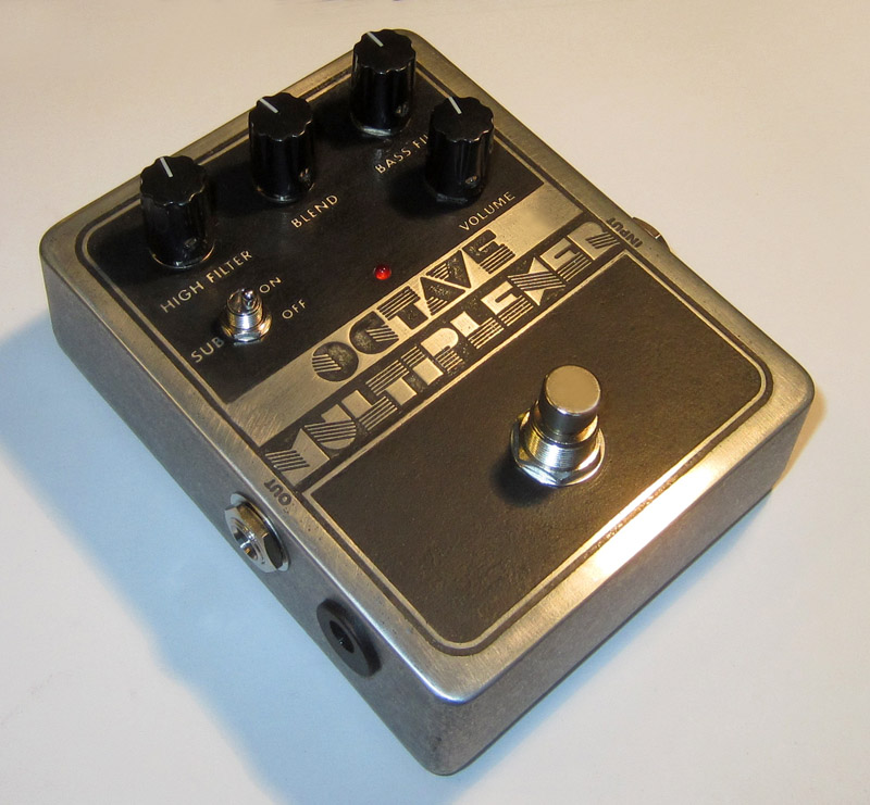
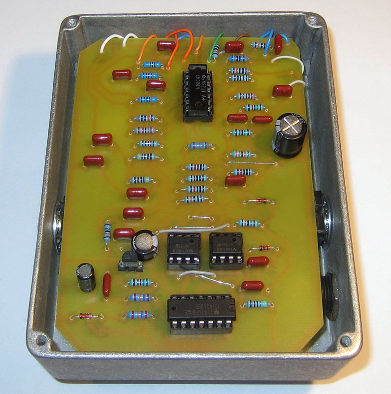
johnk
- Resistor Ronker
I built one about a year ago (I etched a PCB and the enclosure for it) and I love it. I found that it could use a bit more output so I added a Jfet boost to the output with a volume control: