When I look at the datasheets for this chip many times it has a 4.7nF cap in series with a 10 ohm resistor to ground at the output pin 5 before the output coupling cap. So I think the bleed to ground theory is sound.
I might monkey around with a pot as a voltage divider on the inputs and a pot in the gain loop of the first IC. I'm using a NS LM386N1.
Nocentelli wrote:
Whereas in this proguitar shop demo, he has the level knob really high: I am guessing this is massively driving a nice tube amp, and contributes to the smoothing out of the slightly yucky decay (even though, if you watch carefully, he never allows the note to fade out to silence)
I have also noticed this, playing with the circuit in front of an amplifier. If you set the volume high out from the circuit, the ugly decay lessens a bit. Using the JRC386D or the LM386 N-1 also helps a little. I timed the sustain of the three chips I had and the the JRC seemed to consistently work the best. The N-1 is nice too, and the cheapest Tayda 386L ones are noticeably worse. I hate to put things down like that with magic numbers and out of production stuff winning in unscientific tests like this, but I don't think I'm biased here.
Thanks everyone for your work so far. I'm learning a lot
I had some success. The breadboard is still a little noisy but the splatty decay and fizzy artifacts are gone. The biggest improvements were using an isolated power supply instead of a battery and replacing the crap capacitors with good ones. The center section of the circuit still needs some work; both halves sound excellent on their own, it gets noisy connecting them, the 10k got it manageable but there is room for tweaking.
A well shielded enclosure and a ground pour would really help--if I move my hand near the center section of the circuit it picks up a conversation in Mandarin, it sounds like my neighbors using a wireless headset on Skype.
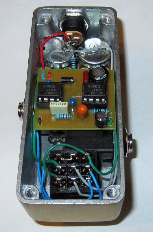
Most of the changes to the prior schems are pulled right from the NS and JRC datasheets.
In his 2006 book "Advanced DIY Effect Pedals" Brian Wampler (Indyguitarist here at FSB) had a very similar circuit to the Acapulco Gold called "386 Fuzz" using two LM386 chips in series like this. Members can find the download link in the Davidoff Library subforum on the #1 PDF file, pages 31-32. There's a ton of useful info in those books.
He suggests a variable 1M voltage divider between the two chips for controlling unruly noise
He leaves Pin 2 on each chip floating (???)
470pF to ground at the input (Pin 3) of each chip
Both chips have the Pin 1 & 8 connected (no cap or resistor)
Hi, guys. I think this pedal sounds great in the clips I've heard. I've been messing around with 386 chips for a while and recently built a Noisy Cricket amp, which gets all of its half watt of oomph from a 386. With the talk of just how loud the Acapulco Gold is, I'm wondering if it will drive a cab. The Cricket will drive an 8ohm Swamp Thang to a reasonable bedroom level. Has anyone tried just skipping a separate amp entirely with this pedal? I'm out of 386s at the moment, or I'd give it a shot myself.
Thanks!
Only with the volume control full on, and even then there will probably still be too much residual resistance compared to the speaker load. Also the 1 uF output cap forms a 20 KHz high-pass filter with an 8 Ω speaker.
Of course there is little you need to modify in order to add a proper speaker output.
Ignorance more frequently begets confidence than does knowledge. (Charles Darwin)
An update: I picked up some 386s to experiment with this circuit. As laid out, it drives an 8 ohm Swamp Thang, but barely. Just for the hell of it, I stuck another 386 on the end of it, basically just doubling the second stage in the schematic, and it absolutely roars. Right now it's super high gain and oscillates when you stop playing -- which may just be due to my sloppy test rig -- but there is a pretty great raging amp tone in there. I need to lay it out properly with shielded cable and a gain control, but I think this might be a cool alternative to the tame Cricket/Ruby/Smokey practice amp circuit.
I just used a C1M at the input.
input to lug 3 and lug 2 to the input of the circuit.
it's basically like rolling you guitar (or bass) volume down.
with it full up, it's like a stock Acapulco gold.