Page 2 of 3
Re: MXR Classic 108 Fuzz
Posted: 04 Apr 2013, 07:45
by Harold
Ripdivot wrote:Cool Harold! I would have finished the trace but I only had the pedal for 1 night. Looking forward to seeing what the buffer looks like.

Mee too

I will first answer some questions like the 47k (R4) and the 47pF (C5) connections before trying to trace the buffer and switching parts.
The buffer switch is a DPDT, so I guess it has the same (milennium) FET switching for the LED as the bypass switch.
Re: MXR Classic 108 Fuzz
Posted: 04 Apr 2013, 11:27
by Harold
Mee = me.
"You cannot edit your posts in this forum" - why?!?

Re: MXR Classic 108 Fuzz
Posted: 04 Apr 2013, 21:53
by Harold
Does the attached schematic make more sense?
Re: MXR Classic 108 Fuzz
Posted: 04 Apr 2013, 21:57
by Harold
Cannot edit my post: missed R2.

Re: MXR Classic 108 Fuzz
Posted: 04 Apr 2013, 23:13
by Harold
How's this for a buffer?
Please mind: this is my second real trace job, the dual layer PCB isn't easy to trace, and I had a couple of these already ...


Re: MXR Classic 108 Fuzz
Posted: 04 Apr 2013, 23:22
by Harold
Since I can't edit my posts, here's the schematic again ... this time with the correct component numbering
Re: MXR Classic 108 Fuzz
Posted: 05 Apr 2013, 12:12
by nooneknows
This makes sense for a simple generic bjt buffer. I generally make buffer like that with a Fet, even simpler, a 1M from gate to ground, drain to V+, Source to a 10K to ground, output capaictor bigger enough, 4 components.
I'm interested in the R13 value: I used a 10K in a buffered FF I built some ago and it worked nice.
thank you
Re: MXR Classic 108 Fuzz
Posted: 05 Apr 2013, 12:33
by Harold
nooneknows wrote:This makes sense for a simple generic bjt buffer. I generally make buffer like that with a Fet, even simpler, a 1M from gate to ground, drain to V+, Source to a 10K to ground, output capaictor bigger enough, 4 components.
I'm interested in the R13 value: I used a 10K in a buffered FF I built some ago and it worked nice.
I still have to double check these:
R1 10k
R2 10k
R3 470k
R4 47k
R5 5M6
R6 680R
R7 100k
R8 1M8
R9 100k
R10 10k
R11 1M1
R12 100k
R13 10k
R14 100k
R15 5M6
R16 330R
R17 47k
R18 100k
R19 100R
R20 5R1
C1 22uF
C2 100uF
C3 2u2
C4 10nF
C5 47pF
C6 10nF
C7 6n8
C8 10nF
C9 4u7
C10 10nF
C11 10uF
C12 22pF
TP1 20k
TP2 100k
TP3 10k
TP4 470kA
TP5 1kB
Q1 BC108
Q2 BC108
Q3 J177
Q4 J177
Q5 J177
Q6 MPS A14
Q7 J177
Q8 J177
Q9 2N5087
Q10 2N5087
There are still a lot of components unaccounted for ... more to come!
Re: MXR Classic 108 Fuzz
Posted: 16 Apr 2013, 17:48
by Harold
Ok, it looks like all the other components are used for the double bypass switching. Is anybody interested in that part of the fuzz?
I mean, I'd love to make a complete schematic for it, but it just will take me a lot of time and I guess nobody really wants to clone that part of the circuit anyway.
Any requests?
Re: MXR Classic 108 Fuzz
Posted: 17 Apr 2013, 19:11
by Harold
Crap: almost forgot ... the 2 blinding blue LEDs.

Now where can I find which resistor I have to raise ... The 330R can't be it and I'm pretty sure the two 5M6's arent either. That leaves me with a 470k (R3), a couple of 100k's (R7, R14, R18) and a 47k (R17). All of these seem rather high for such blinding lights ...
Is it possible the voltage is set with one of the J177 transistors?
Another thing I can't comprehend: the 5mm status led has 0v and 2.8v when engaged, but the buffer LED gets 2.8v and 5.5v? When the buffer is in off position, it get's 2.9 and 2.8v.
Re: MXR Classic 108 Fuzz
Posted: 17 Apr 2013, 22:19
by Harold
I replaced the clear blue 3mm with a diffused red one and the clear blue 5mm with a clear green one.
Sunglasses can be removed now!

Re: MXR Classic 108 Fuzz
Posted: 24 Apr 2013, 12:02
by rugeb
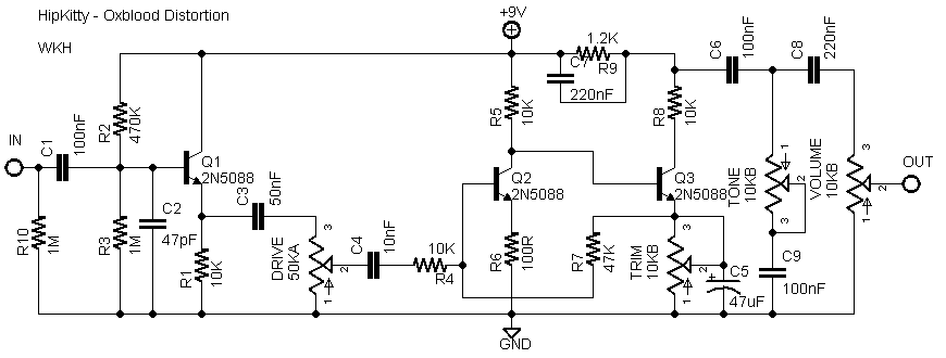
The OXBLOOD DISTORTION: "basically" the same circuit (more or less...)
.
Re: MXR Classic 108 Fuzz
Posted: 01 May 2013, 21:38
by NegationOfNegation
Harold wrote:
R2 10k
Hi Harold,
thanks for your work, the photographs and the schematic.
But, are you pretty shure regarding R2=10k?
Looking at the schematic it seems to be weired, that, voltage over
1k Pot (FUZZ) pot is 0,8 V (that means I_B of Q1 is around 0,8 mA)
and voltage over R6 (0,68kOhm) TP3 (2,75kOhm) and R2 (10kOhm) should
be 3,75 Volts only (Battery = 9,22Volt - U_collector = 5,47Volt).
It makes more sense i.m.h.o., that R2 is 1kOhm only. In that case
all collector resistors of Q1 are 4,4 kOhm * with 0,8 mA is 3,5 Volt approx.
Additionally, on photograph R2 looks like brown black black brown brown,
that means 100*10^1 (and once brown for tolerance) that means 1k.
Have a nice day
Torsten
Re: MXR Classic 108 Fuzz
Posted: 26 Oct 2013, 10:46
by Kejim
Hello gentlemen!
Has anyone had any luck so far with the full schematic of the unit, including the control circuitry and the buffer?|
First of all, i gotta say that i'm really technologically impaired when it comes to fine electronics; I can tell a resistor from a transistor, but that's about it.
My unit got broken (actually, it did arrive broken couple years ago, then a guy makeshift-fixed it with a pot of a different value, but now it died again). Now a guy is trying to fix it, but he said he was having trouble with tracing the exact circuitry that isn't a part of Ripdivot's schematic.
He changed the defective (and also unmatching) makeshift fuzz pot, changed back the values on the 3 little trimmer pots to what looks much like what's on photos in this thread. He also tried to dim the status LED (which he did, not the buffer LED though)
What is a huge problem now, is that the unit is still not working properly (either, some issue was not found, or something was added where it mustn't have been)
The only way the pedal's output is audible now, is with both knobs all the way to the right, and even then it isn't as loud as bypassed signal. If you roll back either of volume or fuzz pots even by a quarter, you can no longer hear anything whatsoever. Adjusting the said 3 little trimpots, while slightly noticeable, doesn't change the bigger picture a whole lot.
I've unscrewed the box to check out the insides of the unit, and there's a whole lotta new parts in there; i'll attach the photos and circle what i've noticed had changed.
A) Looks like it's just a fix (or a backup) of a damaged PCB canal
B) Was definately changed; most likely, by the last guy who looked into it recently. (however, this part of the "before" photo, that i had, was ruined by a camera flash, so it might have been a part of the initial fix). It definately looks different from what I see on pictures in this thread
C, D, E) All of them recent additions; D is labeled "333".
Also, the DPDT switch is changed, though this shouldn't be a concern whatsoever, afaik.
Any bit of help is most welcome! Be it advice, suggestions, or (most importantly!) complete schematics, if anyone has or can get them.
Regards, Dmitry.
Re: MXR Classic 108 Fuzz
Posted: 26 Oct 2013, 10:57
by Kejim
Also, I'm extremely sorry if this post is somewhere in the wrong thread, but that's a thread as relevant as i could find

Also, can't seem to find a way to edit my post.. isn't there one?

Re: MXR Classic 108 Fuzz
Posted: 15 Mar 2014, 15:23
by Chewbacca
Hi,
any news about the buffer?
I've built the one Harold posted on breadboard and tried it without the fuzz.
I buffers, but not very well. Sound is slightly distorted and it filters out a lot of the bass and mids.
This may or may not be intentionally. I was thinking about putting in a clean FET Buffer instead, but could MXR have the buffer designed to be filtering the sound?
Also is there any definite answer to putting the buffer before or after the fuzz?
Thanks, Andre
Re: MXR Classic 108 Fuzz
Posted: 16 Mar 2014, 17:07
by Chewbacca
Did some testing - this is a lousy buffer by itself, but it is absolutely the right thing for the 108 Fuzz. I've tried other buffers and they almost all made the Fuzz go wonky. But this one does the job on the spot.
Thanks Harold
Re: MXR Classic 108 Fuzz
Posted: 16 Mar 2014, 17:57
by Harold
Don't thank me, thank MXR!
Re: MXR Classic 108 Fuzz
Posted: 26 Mar 2014, 19:33
by matt239
Do you really need three trimmers for a fuzz?
Is the usual D.I.Y answer for this to measure all the transistors?
If you just build a fuzz w/o measuring/trimming will you get unpredictable results?
Isn't the gain set by the resistors?
Re: MXR Classic 108 Fuzz
Posted: 26 Mar 2014, 20:20
by IvIark
One biases Q1, one biases Q2 and the other alters the feedback resistance from Q2 emitter to Q1 base. You don't have to put them in of course, but if you don't you haven't got the MXR 108, you've got a Fuzz Face.