Hey folks,
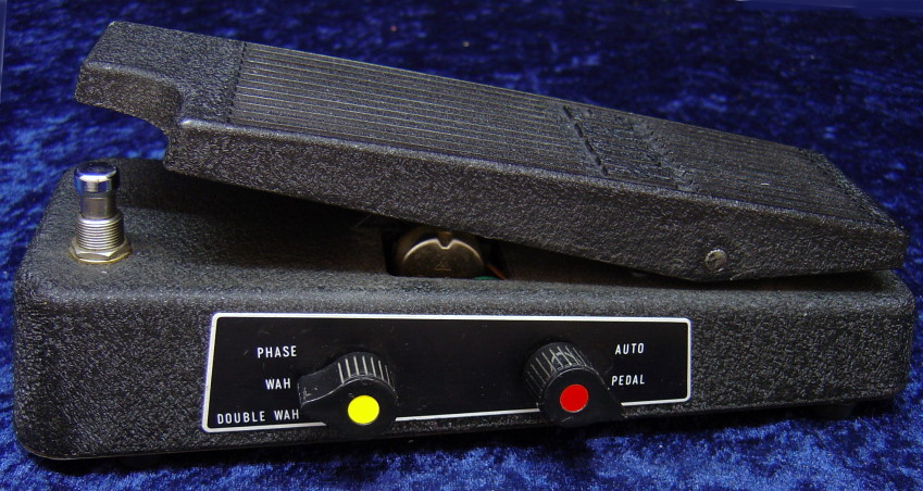
first of all: sorry for unearthing this years old thread! I've been looking for a way to combine wah and phaser sounds for quite a while, and i'm really happy having found the FK-2. An empty Crybaby shell is waiting to get new guts on my working desk, as soon as a new coil of tin arrives by mail. Meanwhile, I simulated a bit in QUCS...
I just want to share my humbe ideas for mods for this lovely pedal, that may (or may not) make the sound more pleasing and may lighten up that switching jungle in the FK-2 a bit, making clone builds easier.
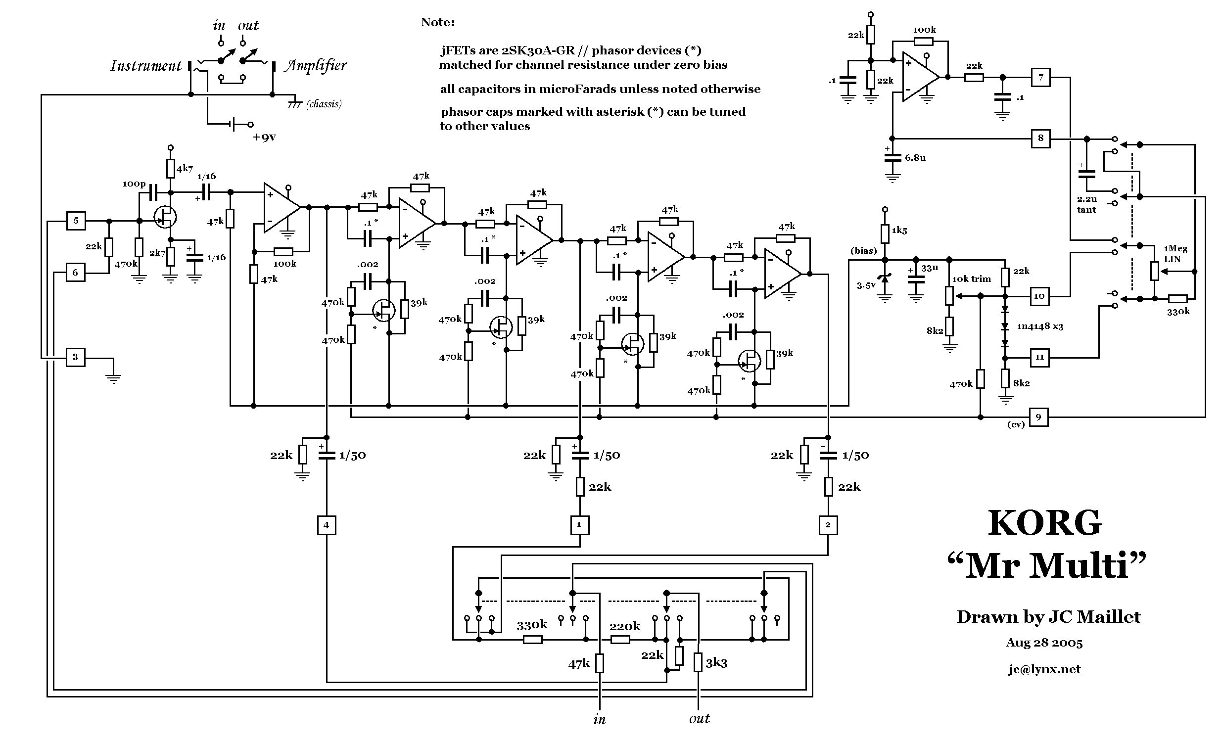
For reference, the schematic as drawn by JC Maillet:
http://www.lynx.net/~jc/MrMulti.gif
Changes to the JC schematic:
-Omitted the 220k and 330k feedback resistors. Similar to the Phase 90 "script mod".
-Changed the first OpAmp (Mixing Amplifier) to an inverting amplifier with a gain of -1 instead of +3. This increases the clean headroom of the filter, saves the inverting JFET stage at that point, and saves some coupling capacitors - the Opamp can be biased like all other opamps, so direct coupling is possible here.
Plans are to put a JFET input stage ahead of the whole thing, to get a decent input impedance suitable for guitars. 47k input impedance seems a bit low to me and might come from Korg's keyboard background...
-Phaser mixing network (2x 47k in my case, see schematic) is always connected. Doesn't do any harm
-22k Output feedback resistor in the wah modes (the one on the 4 pole switch) can be omitted - I couldn't see its benefit in the simulation.
-Wah feedback is not taken from the output of the second phase shifter stage, but from its high pass section. To do that, the high pass is buffered before connecting to the phase shifting mixer. See schematic.
My goal here was to get some degree of peaking lowpass character - similar to what I understand is the response of an inductor wah. The FK-2 originally has a bandpass response.
For simplicity in the simulation, i've placed resistors (zigzag symbol) in the filter instead of the JFET arrangement, to see the filter response at one given center frequency. I've chosen the bias voltage rail as ground rail - once again, for a simpler simulation. Cap values are also arbitrary. Soldering will show if I was right there...
Like this, for the mode switch, a 2P3T on/on/on ("Z type) switch would be enough, instead of a 4P3T rotary switch. More DIY friendly in my opinion...
The Wah feedback resistor is 33k in the schematic, as a moderate value. At 23.5k the resonant peak of the wah will be far into distortion - so for the first opamp a bipolar type like the 4558s might be a good choice for a somewhat graceful sound...
Lower than 23.5k, the resonant peak will get smaller again, and the treble rolloff will be stronger. Lower than 10k may not make much sense... For 33k, we have about 8 dB treble attenuation, should be subtly audible.
Missing in the simulation:
-Input stage and output buffer
-Bias voltage supply
-LFO
-JFETs/Vactrols/4 armed pot turning extraterrestrian minion/...
Hope this all is understandable. Feel free to ask back.
What do you think? Suggestions?
Cheers, Bernhard

