Masa - it's "ground" in polish.
http://www.matronics.com/aeroelectric/a ... ck/mj2.jpg
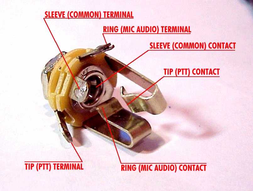
You should connect "in" of your board with tip of input jack, "ground" with sleeve and battery ground with the ring .
"9V" from battery goes to one terminal of DPDT switch and another goes to "+9V" of board
That way you make bypass section with LED. It's not the best solution . You should try Milennium Bypass instead.
Tech 21 - Bass Driver DI [schematic]
-
mozwell

- Breadboard Brother

-
Crowella

- Degoop Doctor
Information
Page 1, first post. Schematics and PCB are in the first link.McWood wrote:Did the links die or did i miss something?
Anybody care to pass the scheme along to me?
For wiring it up: http://twin-x.com/groupdiy/displayimage.php?pos=-2347 (MASA is Ground)
I'm going to try building this thing in a few weeks (christmas build) and hopefully post the results up here (if I remember). After hearing one of these things live and constant nagging by my band mates to get one, what a solution
Hi guys.
I've just built one of these so thought i'd give a build report.
Many thanks to Drkglass for his suggestions and to 12afeal for the schematic and layout.
I havn't got a sansamp or Behringer to compare it to but it sounds great and gives good control over tone and overdrive. and yes you can use 1/4" and xlr at the same time.
At first build i found the outpul level to be a bit low for my needs, it gives instrument level output from the 1/4" jack and i needed line level for recording so after several attempts at adding gain i settled on changing R29 for 47kohm. (i guess i could add a switch between the two for inst/line levels)
This increased the output from the xlr as well so i fitted a 25k pot in place of the R30/R34 divider to give an xlr level control.
There was also a silent spot when the blend is fully anticlockwise and the level pot is fully clockwise, i added a 5.1Kohm resistor between the blend pot wiper and the level pot.
I will also be adding a mids control as this guy has done to his G2 https://www.freestompboxes.org/download/ ... &mode=view thanks to the poster for that one.
I'll also add a ground lift switch by putting a 51ohm resistor and a 10nF capacitor in series between pin 1 of the xlr and ground and connecting the switch between these same points.
I have no need for phantom power but might add it anyway, just in case. can anyone recomend whether i need to take the phantom power feed from both pin 2 and pin 3 of the xlr or will just pin 2 be fine? Why is the feed provided on both pins?
Information
- Posts: 3
- Joined: 23 Dec 2010, 15:40
Hi guys!
I've some questions:
How can I connect a 3PDT switch for true bypass?
Where do I plug the holes "SW1, SW2, SW3?
If I wanted to use a DC-Jack instead of the battery, how should I connect its three pins?
I've some questions:
How can I connect a 3PDT switch for true bypass?
Where do I plug the holes "SW1, SW2, SW3?
If I wanted to use a DC-Jack instead of the battery, how should I connect its three pins?
for true bypass you need to link sw3 to sw2 and connect your switch to the input and output as per any true bypass diagram around the net. it won't true bypass the xlr though. it never will. just doesnt work like that.
for dc jack .... if you don't want a battery at all i'd connect the +ve wire to the centre pin of the jack and the -Ve to the sleeve pin and ignore the 3rd pin.
I use the centre pin for the +ve wire (both battery and circuit board) and connect the battery negative to the switched pin of the jack and the negative wire to the sleeve of the jack but it really depends what power supply you are using (positive tip or negative tip) and what jack you have.
No offence meant, but if you have to ask then you should really get someone who knows this stuff to show you cos it's much easier to show someone than to explain it in words without seeing the jack etc.
Update to my build.
I tried adding a mids control but this doesnt do much as the notch filters really cut the mids so theres nothing left for the control to work with.
Bypassing/removing the notch filters didnt seem to help much either except move the notch around so i put everything back as original and just use the blend control to control the mids, this works because the clean signal is tapped off before the notch filters.
I also got rid of my xlr level control cos it's just not nessesary.
i managed to squeeze it all into a 1590BB box too and modified the original sansamp front panel drawing to suit my needs. i was then able to transfer this to my box in a similar way to using a laser printer to make pcb transfers. i srewed the box lid face down on a slab of mdf with the transfer sandwiched in the middle. then blasted the lid with the blowlamp. if you use label backing paper rather than photo paper to make your transfers it peels off a treat. i'm very happy with the result.
I just need to add my ground lift switch and phantom power now.
Information
- Posts: 3
- Joined: 23 Dec 2010, 15:40
I have the same problem. Can anyone help us?eindrows wrote:my drive pot is not function...
anyone can help me??
i'm so confused...
and the presence pot not function too..
JIMBO_SIR_PSYCHO wrote:I have the same problem. Can anyone help us?eindrows wrote:my drive pot is not function...
anyone can help me??
i'm so confused...
and the presence pot not function too..
Hi.
What´s setting of blend pot?. If the blend pot is in 0 position, the drive and presence pots not function
i hope help you
Regards
Information
- Posts: 3
- Joined: 23 Dec 2010, 15:40
mistral wrote:JIMBO_SIR_PSYCHO wrote:I have the same problem. Can anyone help us?eindrows wrote:my drive pot is not function...
anyone can help me??
i'm so confused...
and the presence pot not function too..
Hi.
What´s setting of blend pot?. If the blend pot is in 0 position, the drive and presence pots not function
i hope help you
Regards
I have solved my problem.
it was just a bad soldering!
thanks anyway!!
yeah, bad soldering..JIMBO_SIR_PSYCHO wrote:mistral wrote:JIMBO_SIR_PSYCHO wrote:I have the same problem. Can anyone help us?eindrows wrote:my drive pot is not function...
anyone can help me??
i'm so confused...
and the presence pot not function too..
Hi.
What´s setting of blend pot?. If the blend pot is in 0 position, the drive and presence pots not function
i hope help you
Regards
I have solved my problem.
it was just a bad soldering!
thanks anyway!!
case closed...
Information
- Posts: 1
- Joined: 27 Sep 2011, 17:17
Hi everyone, i'm new in the forum. My name is Pablo, and i've been working the past couple of days on the SAnsamp driver DI. The only trouble i've got is that I can't get the blend control to work properly. When it is fully anti-clockwise (blend control on 0), works perfectly, but as soon as i turn it clockwise, distortion kicks on of course, but volume goes down a lot, more than 50% down. I replaced pots, capacitors, resoldered the whole board, switch works fine, all controls work fine except for the blend. Could it be that i'm using TL074CN instead of TL074P? Maybe the problem is somewhere else... i attached a photo of the board just in case...
Any suggestions will be greatly appreciated!! Thanks a lot in advance!
Pablo from Argentina.
Any suggestions will be greatly appreciated!! Thanks a lot in advance!
Pablo from Argentina.
- Attachments
-
Hola, Pablo, saludos desde Argentina!
I've built a SanSamp myself but didn't have that problem (or any, for that matter). Check the PCB for bridges. I don't think the TL074 is the culprit (i am using TCL2264/TL07CN myself, no problems) Seems that there is no "CP" for the 74's but only "CN".
Buena suerte!
David
I've built a SanSamp myself but didn't have that problem (or any, for that matter). Check the PCB for bridges. I don't think the TL074 is the culprit (i am using TCL2264/TL07CN myself, no problems) Seems that there is no "CP" for the 74's but only "CN".
Buena suerte!
David
-
rcustoms

- Resistor Ronker
Information
welcome pablo (saludos de colombia),i build this one based on 12rafael layout
http://sites.google.com/site/plexilandia/home
work ok,see you around
regards
rz
http://sites.google.com/site/plexilandia/home
work ok,see you around
regards
rz
Hej!
My name is drazen and Im from croatia. also new at this forum. I had same problems with presence and drive pot, but i can't repair them. i checked whole board, resoldered what was suspicios,but no results. can those who managed to solve their problem tell me what did you resolder to make it work?
My name is drazen and Im from croatia. also new at this forum. I had same problems with presence and drive pot, but i can't repair them. i checked whole board, resoldered what was suspicios,but no results. can those who managed to solve their problem tell me what did you resolder to make it work?
Information
- Posts: 1
- Joined: 13 Mar 2012, 09:24
Hi I'm new to the forum, it seems great!
Just wondering if anyone can tell me why that pins 1 and 3 are swapped on the XLR out? I'd like to add in a ground lift, phase reverse and phantom power blocking caps, so I just want to get a full understanding of the layout!
Many thanks,
Craig
Just wondering if anyone can tell me why that pins 1 and 3 are swapped on the XLR out? I'd like to add in a ground lift, phase reverse and phantom power blocking caps, so I just want to get a full understanding of the layout!
Many thanks,
Craig