Tech 21 - Bass Driver DI [schematic]
-
chicago_mike

- Tube Twister
I'd like to try other opamps, if the pinouts are the same. Like opa's and stuff.
Skyline FX 2013
Information
- Posts: 27
- Joined: 10 Mar 2009, 02:34
You can always create a daughter board with the chips and then "adapt" the pinouts
Information
- Posts: 27
- Joined: 10 Mar 2009, 02:34
Hi again, since I quited this project i've been reading alot for the construction of a SansAmp GT2 (almost the same parts as the triangular ear) and I've confirmed (in my opinion) what I said earlier about the opamps. As it turns out, the TLC2262 or TLC2272 (aparently there is no audible diference between both), and their respective "equivalents" with 4 opamps, are the "secret" behind a lot of Tech21 pedals, namely the GT2 and the Direct Drive. From what i've been reading, the TonePad project for the GT2 is (some say) similar to the Behringer GDI21 witch is like a GT2 built with general use parts and some "errors" (I use "" 'cause some people say that their not errors but rather diferent versions of the same box.
Details asside, there are some testemonies that state that this circuit built with the right IC's (and some minor changes) is and exact copy of the original stuff.
Now that you are all sleaping, lets get to the point, wich is: MAYBE the same analisys can be made regarding the SansAmp BDDI and the BDI21, what I mean exactly is, using TL072 (or TL062) for parts of the circuit where the opamps operate on their linear domain and TLC2262 (or TLC2272) for the cliping zones. This "mod" is rather simple since these chips all have the same pinout and there are quad opamp IC's equivalent to 2 TLC2262.
With some luck the results might be the same as for GT2. There is only one catch, I really don't know were are the clipping sections nigther if using TLC2262 every were afects the overal performance. I would gess not because I think both IC's are equivalent in the linear domain.
So thats it, ill still gona abandon this project for now 'cause I already have a BDI21 wich I like, on the other hand i'll be folowing this and i'm thinking about adapting this circuit to make a DIY version of the SansAmp RBI (according to the Tech21 website is a pumped up BDDI with mid control, fx loop with mix and some other stuff).
-
Rocket Roll

- Solder Soldier
Information
Here it is. Do not forget to connect the "SW2" hole to C20/R48 junction!iloophao wrote:where is on/off ?
(Btw, it works & sounds fine.)
- Attachments
-
-
flood

- Resistor Ronker
Information
i built this thing. it worked fine for a while and i liked the sound a lot. then... i housed it in a bent aluminum chassis, and it died on me. only the LED works, no sound comes through when activated. used nice thick wire, no breaks that i can identify. there was a problem with the enclosure though - it wouldn't ground through the jacks, so i had to use a piece of wire to connect the enclosure to a ground trace, otherwise i'd only get tons of hum (faraday cage hooray!).
anyway, point is that it just won't work now. i don't know if i could be arsed to troubleshoot it or just buy the behringer... i spent a lot of time building it, so i'd love for it to work, though. i can't tell what went wrong with it though.
anyway, point is that it just won't work now. i don't know if i could be arsed to troubleshoot it or just buy the behringer... i spent a lot of time building it, so i'd love for it to work, though. i can't tell what went wrong with it though.
In the interest of full disclosure, I am Animal Factory Amplification.
-
quaternotetriplet
- Resistor Ronker
could someone please post the original schematics?

-
quaternotetriplet
- Resistor Ronker
no i mean the scheme. .
-
quaternotetriplet
- Resistor Ronker
anyone got the scheme with DI?
Hello!
That layout was done by a friend of mine in Chile, 12afael, who's the creator of Plexilandia (main DIy forum in Chile, and probably SA) I actually was the beta tester of that layout when I was living there, and it works fine. I've compared it a Tech21 BDDI and IMO sounds exactly the same .
.
The Phantom/GND Lift section can be added with a 100ohms resistor for current limiting and a 8,2V Zener and a SPDT switchere.
Here's a pic from baaack then .
.
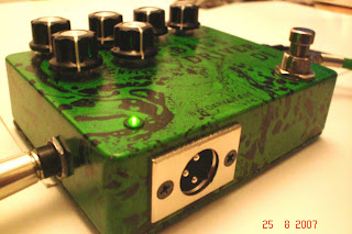
Regards from Finland
That layout was done by a friend of mine in Chile, 12afael, who's the creator of Plexilandia (main DIy forum in Chile, and probably SA) I actually was the beta tester of that layout when I was living there, and it works fine. I've compared it a Tech21 BDDI and IMO sounds exactly the same
The Phantom/GND Lift section can be added with a 100ohms resistor for current limiting and a 8,2V Zener and a SPDT switchere.
Here's a pic from baaack then
Regards from Finland
-
flood
- Resistor Ronker
Information
got mine working again, was a combination of (non-circuit related) issues... bad grounding, bad switch, weird input jack.
can't wait to get it up and running with my 6...
darkglass, where would the 100 ohm and zener go? i'm a bit thick when it comes to XLRs. is this for phantom powering the unit or something? would be useful with my interface at least, since i never gig. if it isn't too much bother, could you draw up a schemo?
In the interest of full disclosure, I am Animal Factory Amplification.
Information
- Posts: 3
- Joined: 28 May 2008, 18:45
has anyone else built this up? I'd really rather not buy the crappy behringer unit if this thing does just as well. I just want to make sure it's confirmed before buying all the parts. Thanks!
*edit* also, can the 1/4" and XLR outputs be used at the same time?
*edit* also, can the 1/4" and XLR outputs be used at the same time?
-
CRBMoA

- Resistor Ronker
I cannot say regarding the DIY layout, but I know that I used to send signal to my rig with the 1/4 and FOH with the XLR. So it works on the production model.ugly_guitar_guy wrote: *edit* also, can the 1/4" and XLR outputs be used at the same time?
atreidesheir wrote: Let's build some damned pedals!
-
flood
- Resistor Ronker
Information
i haven't used the XLR yet, but engaging the SPST definitely disables the 1/4" out on mine. so i guess it doesn'T work here. i wonder if a simple mod couldn't rectify that, though.
In the interest of full disclosure, I am Animal Factory Amplification.
Sorry for the huge delay, I wasn't aware of your question until 1 minute agoflood wrote:got mine working again, was a combination of (non-circuit related) issues... bad grounding, bad switch, weird input jack.
can't wait to get it up and running with my 6...
darkglass, where would the 100 ohm and zener go? i'm a bit thick when it comes to XLRs. is this for phantom powering the unit or something? would be useful with my interface at least, since i never gig. if it isn't too much bother, could you draw up a schemo?
The 100Ohm would be in series with 9V (therefore in series with the battery and DC Jack) limiting the current for the Zener, which would be in parallel with the power supply (look for any Zener Regulator circuit in google and you´ll see an schematic) The advantage of using this technique in this case is that both zener and resistor worsk as reverse polarity protection, current limiting (less current consumption when battery used), and in this case also phantom voltage regulation (from 48V to 8,2V).
Hope you got it.
Regards
Doug
Finland.
just finished populating the board...just some problems...i can't understand the wiring posted...please help...what does MASA mean?..where do i connect it?..and can't see how the input plug is wired...and lastly how is the encircled in black connected?..thanks...
- Attachments
-
- normal_bassdriver.JPG (26.89 KiB) Viewed 5093 times