Hi there, I successfully modified my Joyo British into a VT Bass, thanks to this thread!
For anyone else who wants to attempt the same mod, I have uploaded my own pictorial reference for the part substitutions between the British/VT Bass (based on the tables from this thread). The SMD capacitors/resistors to be replaced are all 0603 (1608 metric) sized.
It sounds pretty much identical with same settings when comparing to VT Bass reviews on YouTube.
I also attempted the speaker sim bypass mod as per viewtopic.php?f=1&t=13545&start=20, but the treble gain is a bit too much even when plugging into the effects return. I think I might attempt the additional 22k-?nf 6db lowpass filter (like the VT Bass V2) with an on-on-on switch later.
I also thought of adding an XLR out by nicking the BDDI's balanced out circuit, but that would mean sacrificing the ample space for the 9V battery. (also I would have to make an layout myself, because there doesn't seem to be a small enough layout that just has that part, which means more work)
Tech21 Character Series [schematic]
Sorry for the old thread
Recently I got Bass Fly Rig, which i almost loved.
However, I play in metal band and personally like open highs.
Speaker sim in this unit is nice, but cuts all the highs above ~4kHz.
Turning higs up actually adds clank, but nothing in the air
I don't want to make speaker sim defeat, moving low pass freq will be better
I found two ways in this thread
1) bajaman's advice will be reducing R14:
*guessing Bass fly rig will be another story...
Recently I got Bass Fly Rig, which i almost loved.
However, I play in metal band and personally like open highs.
Speaker sim in this unit is nice, but cuts all the highs above ~4kHz.
Turning higs up actually adds clank, but nothing in the air
I don't want to make speaker sim defeat, moving low pass freq will be better
I found two ways in this thread
1) bajaman's advice will be reducing R14:
2) Darkglass advising increasing R18:R14 is reduced from 47k to 33k in the British - Only a slight difference in the high frequency rollof characteristic ( British = 4.8khz, and Blonde = 4.2khz) I guess this is the difference with the Celestion speaker response model in the British compared to the Jensen speaker response model in the Blonde
Which way do you think will be better, or may be another one? Thank you!For getting the same funcioality as the new Character pedals, I would increase the value of R18. In the Liverpool is 33k, I would try anything from 47k to 100k.
*guessing Bass fly rig will be another story...
Looking at the schematics posted, I noticed that R5 is not consistent between models.
This is part of the buffer stage and forms an R-C network with C2.
Also is anyone knows what R5 is on the Joyo pedals, please share.
This is part of the buffer stage and forms an R-C network with C2.
Also is anyone knows what R5 is on the Joyo pedals, please share.
R5 is likely R5 on the Joyo, but I'm not sure about the Tech21 v2. If anyone has this info, please share!thehallofshields wrote:Looking at the schematics posted, I noticed that R5 is not consistent between models.
This is part of the buffer stage and forms an R-C network with C2.
Also is anyone knows what R5 is on the Joyo pedals, please share.
Stupid question:bajaman wrote:I would suggest trying a value of 1n (possibly more) for the capacitor marked with a ?
This sets the high frequency rolloff when the speaker simulator cabsim switch is disengaged.
For the suggested value the high frequency response will be approximately -3db down at 8KHz.
Double the value (2n2) and the response will be -3db at 4Khz.
cheers
bajaman
I have a VT bass v2 and if I would remove 6dB per octave high roll off filter when a sim Cab is disengaged just remove this cap marked with "?" ?
But this problem can also be bypassed by putting an equalizer pedal and boosting of 6db the 4.5khz?
Thanks

Too bad no one seems to have the values for the Leeds and California pedals, it would be very interesting and educational.
i ll never get tired of saying those pedals are brilliant ( i have the blonde and the liverpool)!
i ll never get tired of saying those pedals are brilliant ( i have the blonde and the liverpool)!
Information
- Posts: 4
- Joined: 26 Mar 2012, 04:40
- Completed builds: Stage Center Reverb
GGG Rat
BYOC LPB1 (or whatever it's called)
Boss SD1 Five Star Germanium
NYC Big Muff Mid Boost
JCM800
...too many to keep track of - Location: Zanesville, OH
- Contact:
Hey medvege. Did you ever find an answer or make an attempt at the R14/R18 mod? I have a Blonde that seems too dark. I would like the highs to be more extended but can't find any info anywhere.
-
jhergonz

- Breadboard Brother
Done reading this whole thread, and this is awesome! thanks to all of you guys for the information you shared! this is very educational. 
can anyone tell me if there are differences between the various character modules?
I opened my hot rod plexi and found that it is very similar to the character series. the character module is ch33-10. Does the number represent the revision or is it a model identifier?
I opened my hot rod plexi and found that it is very similar to the character series. the character module is ch33-10. Does the number represent the revision or is it a model identifier?
I made bode plots of the voice control operation of the the four Joto "sound" models. It appears that the Actone, American and British models are all very similar, the main difference mostly being the particular band stop frequency in the middle.
The California Sound's voice knob has a wildly different function from the other three, more like a very broad high pass attenuation.
The way they all roll off below 100Hz and above 4kHz must be the combination speaker + microphone dynamic, because the speakers themselves typically respond past 5kHz.
All of the other knobs are set to 12. The input voltage was 50mV.
Dear all, I'm interested to the Tech21 British Schematics but I can't find the thread.
Somebody can uplad it again or send me a PM with the latest scematics?
Somebody can uplad it again or send me a PM with the latest scematics?
I know this is a super old thread, but hopefully someone can answer this: If you had a defective CH34-4 module, how would you go about fixing it?bajaman wrote: ↑13 Aug 2009, 12:36 Well here is what I found with the British
First - the CH34-5 module is identical internally to the CH34-4 module used in the Blonde and the VT Bass models.
I removed the module and thanks to mxrmxr and dimebuGG I was able to measure most of the resistor values (except the one from the junction of the zeners which is open circuit in the CH34-4 module). They are identical to the values measured by mxrmxr. At this stage I was going to put the module back in the mainboard but decided to crack it open just to be sure. I need not have bothered because it is identical internally - the same smd zeners and the same TLC2262 dual op amp.
It looks like Jim was right on here
Can anyone share how they removed the super hard goop from the module?
If I get access to the IC I think I can replace it. (I was an electronics tech for about 2 decades)
As an alternative, is it better to just re-build the module?
Thanks in advance for any help!
One more thing: thank you ALL for this thread. It's been such a joy going through each post and following your steps toward drawing these schematics. I couldn't be more grateful.
Gentlemen.
I´ve been looking for this schematics for a long time and I found only another topics... So I decide to reverse the pedal by myself... It took awhile but I did... After it I post the schematic on other topic and JIM told me about this topic... I am ripping me on angry...
Anyway... Here is my drawing of the Joyo Amp simulator peda, with the component alias as on the Joyo PCB. It is the same as used on Waldman pedals also (use the same PCB). Some values are different from the values you have on the tables because this are the values I measure on the components on the pedal I have. It is possible they are different for a fabrication batch reason.
Here are the schematic for the three most common versions, British, American and AC Tone (Liverpool). All capacitors have been measured offboard by me and some of them have different values from those already found from other coleagues. It may be from some fabrication lot or other unknow reason...
Feel free to make comments.
Best regards
Daniel.
Edit - I replace the American Sound schematic version. This new one have some corrected values...
- Attachments
-
 AC Tone Schematic.pdf
- (152.39 KiB) Downloaded 308 times
-
- British Sound Schematic.pdf
- (153.09 KiB) Downloaded 325 times
-
- American Sound Schematic.pdf
- (153.13 KiB) Downloaded 361 times
Here it is.... 1590BB PTH full on board design...
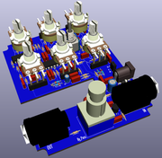
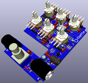
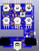
Now it is just to make some adjustments and optimization and prototype... I add a switch to turn On/Off the CabSim....
Comments are welcome.
Regards.
Daniel.
Now it is just to make some adjustments and optimization and prototype... I add a switch to turn On/Off the CabSim....
Comments are welcome.
Regards.
Daniel.
-
modman

- a d m i n
Information
- Posts: 4898
- Joined: 19 Jun 2007, 16:57
- Has thanked: 4411 times
- Been thanked: 2139 times
Daniel,
The search function within phpbb forum software has serious limitations, and there is no easy solution, it seems... I may help to use the advanced search and only search topic titles... but it feeds off the same engine. Numerous times did I start a topic on this or that pedal, only to discover in the 'similar topics' listing below, that a thread already existed...
impressive effort nonetheless - thanks so much for sharing
Please, support freestompboxes.org on Patreon for just 1 pcb per year! Or donate directly through PayPal
I've been reading through this thread (and a couple others), specifically interested in the 'cab bypass' that some have done. I have the behringer clone of the sansamp GT2 (tm300 'tube amp modeller') and the character is quite nice but is incredibly muffled when run through an amp FX return into a guitar cab.
Based on danielp's schematics above it looks like the low pass filter is made up of IC1A and IC1B, and jumping after R24 (33k) to R28 (0R), and cutting a trace, bypasses this low pass.
the sansamp GT2 uses the same low pass circuit (followed by the 'mic position' selector), and the behringer TM300 follows the GT2 schematic.
GT2 schematic:
in this schematic, the low pass filter is made from IC3A and IC3B. different IC numbering on the board of the TM300 but circuit is the same. So a jumper after the 10k (the one after IC2B) to the 10k / .01uf (after IC3B), and a cut trace right after IC3B, and the low pass filter is bypassed. Much more treble content so it does not sound muffled running into a power amp and guitar cab. The 'mic position' switch is still in the circuit but in the 'center' position it is essentially bypassed so no harm in leaving that in the circuit.
one cut trace on the top of the board below the middle switch
and one jumper under the board
It could be made switchable but I have no interest in ever running direct.
Somewhat interestingly, the tm300 uses two TL074's and one 4558. But only two of the four op amp stages in each of the TL074's appear to be used. I wonder why they didn't just use one TL074.
I may pick up that Joyo British sound pedal anyway as a midrange control would be nice.
Based on danielp's schematics above it looks like the low pass filter is made up of IC1A and IC1B, and jumping after R24 (33k) to R28 (0R), and cutting a trace, bypasses this low pass.
the sansamp GT2 uses the same low pass circuit (followed by the 'mic position' selector), and the behringer TM300 follows the GT2 schematic.
GT2 schematic:
one cut trace on the top of the board below the middle switch
Somewhat interestingly, the tm300 uses two TL074's and one 4558. But only two of the four op amp stages in each of the TL074's appear to be used. I wonder why they didn't just use one TL074.
I may pick up that Joyo British sound pedal anyway as a midrange control would be nice.