After a lot of web search I gave up to find the schematic of the rocktron austin gold, it's a overdrive I really like, and use a lot. sadly it is not made super strong.
I posted in this forum the request for a schemo.... but I had no answer
"You've converted me to Cubic thinking. Where do I sign up for the newsletter? I need to learn more about how I can break free from ONEism Death Math." - Soulsonic
Yes, it is is true. Mark M. said he had some problem on the output.
Anyway, I don't want to rebuild or clone completely the austin gold, but just get the secret of it sound. The prebass is, to my ears, a fine tone shaping device (from TS to bass heavy drive sounds).
I would like to put it in some upcoming project. I would like to mimic the tone of the pedal with transistors (will it be possible?)
The output looks funny. Perhaps some bypass switching components (fets, etc.) were eliminated from the schematic, while others were left behind. (Speaking from experience... )
<edit> Bernard - did you use FET opamps? They might not like this circuit.
This is my first post. Thank you for all the info here.
Tha Austin Gold is one of my favoite pedals. I also traced it and believe the schematic above is correct. But the bypass part is omitted. The "old" rocktron pedals use 4066 analog switch IC to do the bypass part. (The "new" ones use sth like the BOSS.)
To my knowledge, when using analog switches to trun on/off audio signals, the 2 sides of the switch should be bisaed to the same level. Also a cap in one side of the analog switch. All these parts are for avoiding the "pop" sound.
I am talking about the C7/R8/R10/C8. I do not want to take my Austin Gold apart again. But I pretty sure there is a analog switch between C7 R8 & R10 C8, in series with R9. Of course, some parts have other duties except for the bypass.
Tone wise, the 4066 method is better than BOSS in my book.
For the Jonas' schematic, there seems to be something wrong with the connections for vcc2 and ground.
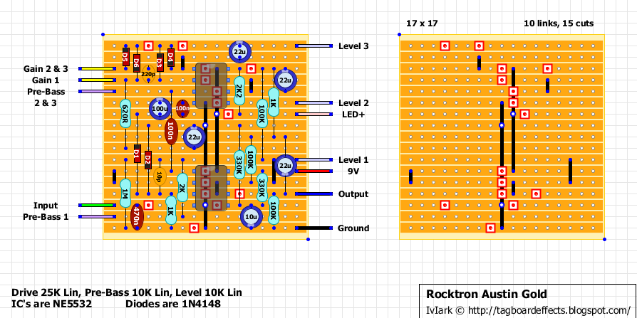
For the PDF schematic, that 22µ coming from drive pot through 620R needs to be reversed. I just finished Mark F's layout, and it's now verified, with that cap reversed. This means that the PDF schematic should also be considered as verified - after that cap has been reversed. It's negative to ground...
"If anyone is a 'genius' for putting jacks in such a pedal in the only spot where they could physically fit, then I assume I too am a genius for correctly inserting my legs into my pants this morning." - candletears7 - TGP
Yes. Negative to ground, if ground is a lower voltage than whatever is connected to the other side of the cap..
In my schematic both sides of the capacitor are essentially at the same 4.5V bias. So there is no correct orientation.
The 22µ cap can be connected to either 4.5V or 0V. Won't change the sound, AC signals don't care that much what "ground" is..
Connecting it to ground instead of VCC/2 is better. And makes polarity way easier. Negative to ground.
I've got one here for repairing. The capacitor in series with 620r is 22u and it is oriented with + side to vcc or gnd (didn't check if it's ground or vcc but it is oriented reversed from the way we usually see). CIs are JRC5532DD, HD14016BP (instead of 40106N) and HD14584BP (instead of 4016N). Apart from that, the schematic posted by Jonas Sjöberg is accurate and all the connections match. The version I had at hand used smd resistors and capacitors. I Could check only the electrolytic caps and the values he posted are correct.
I've got one here for repairing. The capacitor in series with 620r is 22u and it is oriented with + side to vcc or gnd (didn't check if it's ground or vcc but it is oriented reversed from the way we usually see). CIs are JRC5532DD, HD14016BP (instead of 40106N) and HD14584BP (instead of 4016N). Apart from that, the schematic posted by Jonas Sjöberg is accurate and all the connections match. The version I had at hand used smd resistors and capacitors. I Could check only the electrolytic caps and the values he posted are correct.


