Music Man Stingray Preamp  [schematic]

All about modern commercial stompbox circuits from Electro Harmonix over MXR, Boss and Ibanez into the nineties.
Post Reply
User avatar
Sweetalk
Solder Soldier
Information
Posts: 152
Joined: 12 Dec 2009, 04:13
Has thanked: 22 times
Been thanked: 18 times

Post by Sweetalk »

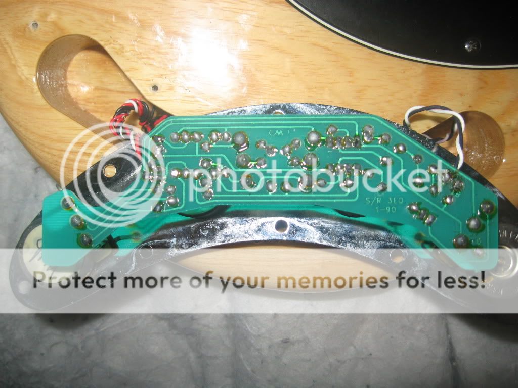
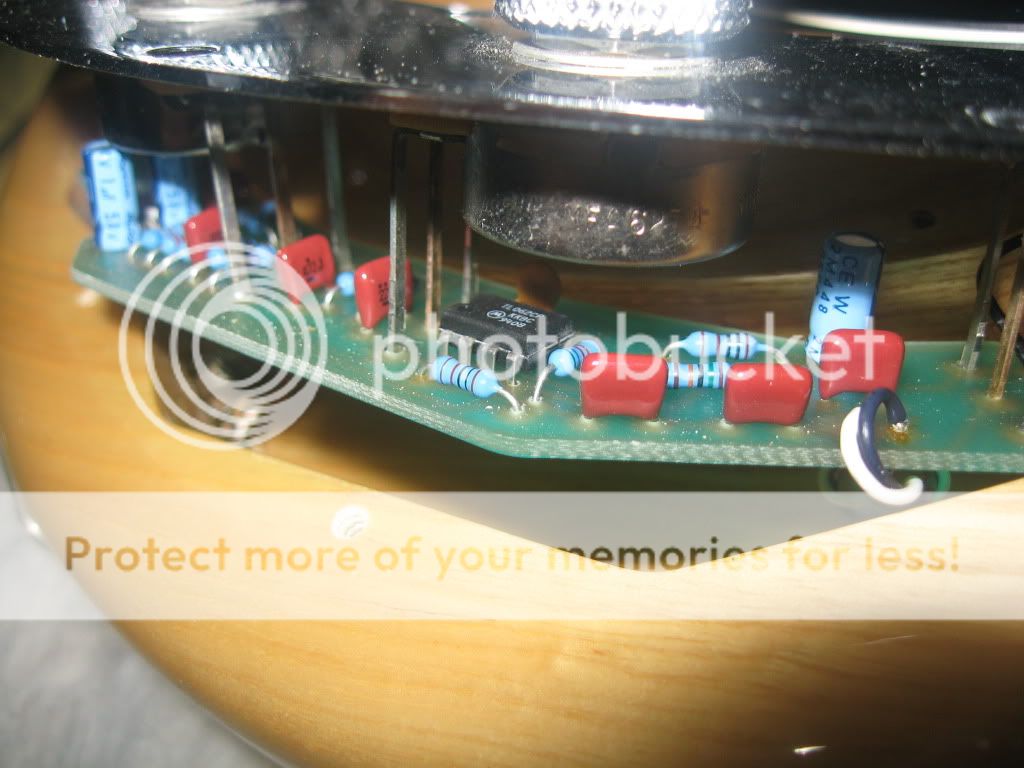
Hi all!, this is not an stompbox but it's a very interesting circuit. Here are some pictures, when I return from my vacations I start the tracing. Helps is welcome!! :mrgreen: The IC it's a Motorola TL062CP

Image
Image
Image
Image
Image

User avatar
sinner
Old Solderhand
Information
Posts: 4709
Joined: 06 Nov 2008, 17:16
Location: ...no more
Has thanked: 1031 times
Been thanked: 909 times

Post by sinner »

Hi :) Thanks for that, can you extend red line on the last photo to green line and tell me how long it is in mm's?

Thanks
Pawel

User avatar
lolbou
Old Solderhand
Information
Posts: 2617
Joined: 18 Nov 2008, 21:38
Has thanked: 308 times
Been thanked: 225 times

Post by lolbou »

Ever been through this viewtopic.php?f=13&t=431&hilit=sabre? Anyway, I think it's been done already http://pds.exblog.jp/pds/1/200705/26/62 ... 322510.gif... 'Course it might be checked and a layout could be drawn if needed!

Thanks for the inside pics ("my" bass player don't really like to have his basses opened...) though.

Edit: and nice stuff here http://www.musicmanbass.org/mycustompage0019.htm... :D
- Are you a mod or a rocker?
- Uh, no, I'm a mocker.

User avatar
Silent Fly
Resistor Ronker
Information
Posts: 424
Joined: 27 Feb 2008, 22:40
Has thanked: 27 times
Been thanked: 48 times

Post by Silent Fly »

lolbou wrote:(...) Anyway, I think it's been done already http://pds.exblog.jp/pds/1/200705/26/62 ... 322510.gif(...)
Interesting thanks!

Do you know why some components are in a blue rectangle?
"Remember - all I am offering is the truth, nothing more". Morpheus

User avatar
Sweetalk
Solder Soldier
Information
Posts: 152
Joined: 12 Dec 2009, 04:13
Has thanked: 22 times
Been thanked: 18 times

Post by Sweetalk »

lolbou wrote:Ever been through this viewtopic.php?f=13&t=431&hilit=sabre? Anyway, I think it's been done already http://pds.exblog.jp/pds/1/200705/26/62 ... 322510.gif... 'Course it might be checked and a layout could be drawn if needed!

Thanks for the inside pics ("my" bass player don't really like to have his basses opened...) though.

Edit: and nice stuff here http://www.musicmanbass.org/mycustompage0019.htm... :D
I checked those but are from the Sabre, this is the Stingray :mrgreen: :mrgreen: , unless they're the same circuit but with different IC :scratch: . This one has Bass, Treble and Mids.

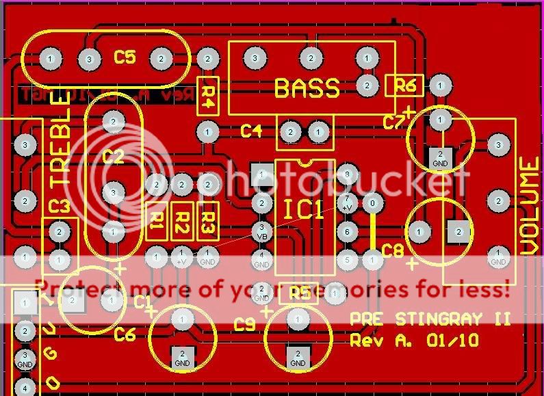
I made a Layout for a vintage Stingray pre, I post it later (with Bass and Treble controls).

Image

User avatar
lolbou
Old Solderhand
Information
Posts: 2617
Joined: 18 Nov 2008, 21:38
Has thanked: 308 times
Been thanked: 225 times

Post by lolbou »

Read better, the original Stingray Bass preamp is here as well... :wink:
Silent Fly wrote:Do you know why some components are in a blue rectangle?
Nope, no hablo japano :mrgreen: ...
- Are you a mod or a rocker?
- Uh, no, I'm a mocker.

User avatar
Sweetalk
Solder Soldier
Information
Posts: 152
Joined: 12 Dec 2009, 04:13
Has thanked: 22 times
Been thanked: 18 times

Post by Sweetalk »

lolbou wrote:Read better, the original Stingray Bass preamp is here as well... :wink:
Silent Fly wrote:Do you know why some components are in a blue rectangle?
Nope, no hablo japano :mrgreen: ...
Ups!!! I didn't saw it :oops:

User avatar
george giblet
Resistor Ronker
Information
Posts: 404
Joined: 30 Dec 2008, 17:27
Has thanked: 206 times
Been thanked: 309 times

Post by george giblet »

http://pds.exblog.jp/pds/1/200705/26/62 ... 322510.gif

Looks pretty good. This schematic is slightly different to what I've seen and checked over in the past.

It shows:
- Input filter 130k not 150k
- Middle resistors 3k6 not 3k9
- Bass resistors 6k2 not 6k8

Are these variations in the newer models or mistakes?

The blue lines surround parts which affect the bass response. Many moons ago a Japanese guy had a site which modified these parts, it could be the same guy or a spin-off schematic.

User avatar
HENK
Breadboard Brother
Information
Posts: 50
Joined: 05 Sep 2008, 17:15
Has thanked: 312 times
Been thanked: 5 times

Post by HENK »

Hello!
Is it possible to need it as a Standalone/Stompbox Preamp?
Greets Thilo

User avatar
quaternotetriplet
Resistor Ronker
Information
Posts: 374
Joined: 19 Nov 2008, 13:37
Has thanked: 10 times
Been thanked: 6 times

Post by quaternotetriplet »

anyone who have redrawn the scheme? can save the one posted on the japanese site.

User avatar
mictester
Old Solderhand
Information
Posts: 2924
Joined: 11 Sep 2008, 20:29
my favorite amplifier: Mesa Boogie, Roost Sessionmaster, AC30
Completed builds: Hundreds! Mostly originals, a few clones and lots of modifications.
Location: Somewhat closer to Amsterdam than before!
Has thanked: 32 times
Been thanked: 845 times
Contact:

Post by mictester »

quaternotetriplet wrote:anyone who have redrawn the scheme? can save the one posted on the japanese site.
Please do! :thumbsup
"Why is it humming?" "Because it doesn't know the words!"

User avatar
pedalgrinder
Cap Cooler
Information
Posts: 548
Joined: 29 Aug 2011, 06:05
my favorite amplifier: Ampeg SVT
Completed builds: pedals with pots switches and everything
Location: South Australia Adelaide
Has thanked: 198 times
Been thanked: 173 times

Post by pedalgrinder »

hmmm interesting high pass filter with tone stack to stop feedback and to get full sound out of it once filtered
What's the best thing about fat chicks and scooters? There both fun to ride around until your mates find out!

User avatar
deltafred
Opamp Operator
Information
Posts: 1654
Joined: 06 Apr 2010, 16:16
Location: England
Has thanked: 814 times
Been thanked: 306 times

Post by deltafred »

The high pass filter straight after the pickup is to protect the speaker/s if you damp the strings with your hand. It is a nice feature to be built into a bass, most don't have that. It is amazing how much the speaker jumps when you do that without a HPF, especially if you have a bass amp that is good down to 10Hz (+/- 3db). Without looking it up I believe it is 12db/octave roll off.

It is quite surprising the MM 3 band preamp gets such a bad press compared to the older 2 band (see the Baja thread) among bass players as it is a really nice preamp but I suppose it is down to nostalgia, mojo and the general trend to prefer older instruments or designs to newer ones . I have both 2 and a 3 band MM basses and like them both equally but I am not one to be swayed by popular opinion and make my own mind up.

I thought I had a redrawn schematic but it is incomplete. If I get it tidied up before someone else posts it then I will.
Politics is the art of so plucking the goose as to obtain the most feathers with the least squawking. - R.G. 2011
Jeez, she's an ugly bastard, she makes my socks hurt. I hope it's no ones missus here. - Ice-9 2012

User avatar
pedalgrinder
Cap Cooler
Information
Posts: 548
Joined: 29 Aug 2011, 06:05
my favorite amplifier: Ampeg SVT
Completed builds: pedals with pots switches and everything
Location: South Australia Adelaide
Has thanked: 198 times
Been thanked: 173 times

Post by pedalgrinder »

how would you go about putting a preamp like this in a bass that has a dual pickup like a precision bass and a single pickup back further like a jazz bass. or are you pushing shit up hill. does it only connect to the one pickup?
What's the best thing about fat chicks and scooters? There both fun to ride around until your mates find out!

User avatar
deltafred
Opamp Operator
Information
Posts: 1654
Joined: 06 Apr 2010, 16:16
Location: England
Has thanked: 814 times
Been thanked: 306 times

Post by deltafred »

A word of warning, I simulated the hand drawn circuit given above as I was considering using it in a rack mounted preamp. For some strange reason only the treble control affects the frequency response, the middle and bass do nothing.

The schematic looks ok to me at first glance but I haven't had time to get to the bottom of it yet so if anyone else fancies simulating it then please do. I don't know if this is a bug in my sim program (QUCS - Linux) or a schematic error.
Politics is the art of so plucking the goose as to obtain the most feathers with the least squawking. - R.G. 2011
Jeez, she's an ugly bastard, she makes my socks hurt. I hope it's no ones missus here. - Ice-9 2012

User avatar
george giblet
Resistor Ronker
Information
Posts: 404
Joined: 30 Dec 2008, 17:27
Has thanked: 206 times
Been thanked: 309 times

Post by george giblet »

I'm not sure what is wrong with you simulations. (Maybe there is something wrong with you pot models?)

It's a common circuit and I have simulated this ckt many times. It does work.

User avatar
deltafred
Opamp Operator
Information
Posts: 1654
Joined: 06 Apr 2010, 16:16
Location: England
Has thanked: 814 times
Been thanked: 306 times

Post by deltafred »

george giblet wrote:I'm not sure what is wrong with you simulations. (Maybe there is something wrong with you pot models?)

It's a common circuit and I have simulated this ckt many times. It does work.
Thanks, that is just what I wanted to hear as I couldn't see anything wrong with the circuit.

I am sure I have simulated in the past with no problems. I haven't had a chance to get to the bottom of it yet. My thoughts were that it could be a bug in QUCS or something odd in my file. I will start from scratch, rather than edit an old file, and see if that works.
Politics is the art of so plucking the goose as to obtain the most feathers with the least squawking. - R.G. 2011
Jeez, she's an ugly bastard, she makes my socks hurt. I hope it's no ones missus here. - Ice-9 2012

Post Reply