Are you going to post them... ?mictester wrote:There are a couple of equivalents, but they are obsolete, and incredibly expensive (if you actually manage to find any). You should do exactly what DOD did - they used an LM13600 instead. The 13600 is a dual OTA, where the 4094 is a single one. Both are equipped with optional output Darlington buffers. My FX25 work-alike uses a TL074 quad and a 13600. It sounds exactly like the original, and cost next to nothing to build. It also has the advantage of an output buffer, and "true bypass". I've done another version using CMOS bypass switching too, which uses a more reliable switch (a momentary type) but still sounds the same!czech-one-2 wrote: Is there an equivalent more common ic with a pin for pin match.? If anybody knows could you share that with me?
DOD - FX25 Envelope Filter [schematic]
-
Barcode

- Diode Debunker
-
mictester

- Old Solderhand
Information
The immediately obvious "equivalent" IC is the BA662. I have a strip of these from about 25 years ago! I can't remember another similar single OTA, but there were several.Barcode wrote:Are you going to post them... ?mictester wrote:There are a couple of equivalents, but they are obsolete, and incredibly expensive (if you actually manage to find any). You should do exactly what DOD did - they used an LM13600 instead. The 13600 is a dual OTA, where the 4094 is a single one. Both are equipped with optional output Darlington buffers. My FX25 work-alike uses a TL074 quad and a 13600. It sounds exactly like the original, and cost next to nothing to build. It also has the advantage of an output buffer, and "true bypass". I've done another version using CMOS bypass switching too, which uses a more reliable switch (a momentary type) but still sounds the same!czech-one-2 wrote: Is there an equivalent more common ic with a pin for pin match.? If anybody knows could you share that with me?
There is no point whatsoever in going for "authenticity" in a circuit like this. Just use the 13600 or 13700 and either a quad op-amp or a pair of duals - it will sound just like the original. A useful trick is to put an insert point into the input of the sidechain. This allows you to put unaffected guitar signal in there, and put the filter part after your favourite distortion device. You can then get amazing autowah fuzz sounds!
"Why is it humming?" "Because it doesn't know the words!"
-
bigorangefan79
- Breadboard Brother
The reason I asked about the ca3280 is because I have a couple and would like to finish up a fx25 perf that I started in hopes of parts I've already got. I've made a perf with the ca3280 pinout in mind, put the .01 caps to ground at the output of each ota since it does not have built in buffers, and ran 9v to both V+'s. It wahs alright but as the signal dies, it distorts and sputters. Any insight on needed component value and/or placement changes, or things to check for would be appreciated.
-
mictester
- Old Solderhand
Information
It sounds like you're going in the right direction. Can you put your schematic up here? Then we'll be able to suggest improvements.bigorangefan79 wrote:The reason I asked about the ca3280 is because I have a couple and would like to finish up a fx25 perf that I started in hopes of parts I've already got. I've made a perf with the ca3280 pinout in mind, put the .01 caps to ground at the output of each ota since it does not have built in buffers, and ran 9v to both V+'s. It wahs alright but as the signal dies, it distorts and sputters. Any insight on needed component value and/or placement changes, or things to check for would be appreciated.
"Why is it humming?" "Because it doesn't know the words!"
-
bigorangefan79
- Breadboard Brother
mictester wrote:It sounds like you're going in the right direction. Can you put your schematic up here? Then we'll be able to suggest improvements.bigorangefan79 wrote:The reason I asked about the ca3280 is because I have a couple and would like to finish up a fx25 perf that I started in hopes of parts I've already got. I've made a perf with the ca3280 pinout in mind, put the .01 caps to ground at the output of each ota since it does not have built in buffers, and ran 9v to both V+'s. It wahs alright but as the signal dies, it distorts and sputters. Any insight on needed component value and/or placement changes, or things to check for would be appreciated.
- Attachments
-
- fx25-ca3280
-
candletears7
- Solder Soldier
I just got one of these in, and its distorting like a bitch? Apparently this is pretty common in thd old 2 knob fx25. Any ideas before I start probing?
-
candletears7
- Solder Soldier
Fixed!
Dodgy electrolytic
Dodgy electrolytic
-
rocklander

- Old Solderhand
Information
- Posts: 2726
- Joined: 18 Apr 2008, 11:33
- my favorite amplifier: my jansen bassman 50
- Completed builds: rebote 2.5; supreaux; odie; heartthrob tremolo; ross phaser; dr. boogey; thor; baja black toast; slow gear attack, rebote, tri-vibe, small clone, little angel, magnus modulus, echo base, hex fuzz, big muff, 22/7.
- Location: Rotorua, New Zealand
- Has thanked: 1406 times
- Been thanked: 231 times
- Contact:
I've made a layout for 1590a (yet to be etched and verified, so if anyone wants to go over it as a second pair of eyes, I'd really appreciate it). looks right so far, but will check again then build to see how it goes.trevize wrote:this one?
I heard amazing samples of this auto wah, very "synthy".
http://topopiccione.atspace.com/PJ11DODfx25.html
did not include the Schem as it's not mine to do so, but available at link posted above.
pdf is for A4 paper. red is 9V, brown is VB
- Attachments
-
 dod-fx25-pcb-layout3.02.pdf
- (192.03 KiB) Downloaded 219 times
world's greatest tautologist ...in the world
Ronsonic wrote:...the lower the stakes the more vicious the combat.
atreidesheir wrote:He should be punched in the vagina.
Information
- Posts: 2
- Joined: 06 Jan 2014, 23:53
Hey guys, I am installing a Deville (Mammoth Electronics) Click-less true bypass in this pedal. I need to have the pedal "always on" so I followed Ice-9's directions on the first page and removed Q1 (the J201 mislabeled as Q2) and removed Q2 (the J113) and jumpered the d and s legs. However, its not working now and just sounds like a high pass filter with no sweep.
Does anyone know how to do this correctly?
Does anyone know how to do this correctly?
Information
- Posts: 2
- Joined: 06 Jan 2014, 23:53
Anyone? It would be much appreciated!

Here is sound https://dl.dropboxusercontent.com/u/209 ... odfx25.mp3 And my tweaked layout for bass with blend. But I have a one trifle: when we add decay knob, it's work good, but bias voltage on cap is drop down (when we tune this knob). Bias need to be 0,9v on electrolytic cap for a clean first attack. I don't have time for resolve it. (Adding 470-1k attack resistor don't resolve it) Solution is find way to have and hold starting bias voltage on 0,9v then cap will charge to 2,5v. Please comment if you have suggestions.

-
Blitz Krieg
- Breadboard Brother
i wish that song would play every time i log into this sitepiod wrote:Here is sound https://dl.dropboxusercontent.com/u/209 ... odfx25.mp3 And my tweaked layout for bass with blend. But I have a one trifle: when we add decay knob, it's work good, but bias voltage on cap is drop down (when we tune this knob). Bias need to be 0,9v on electrolytic cap for a clean first attack. I don't have time for resolve it. (Adding 470-1k attack resistor don't resolve it) Solution is find way to have and hold starting bias voltage on 0,9v then cap will charge to 2,5v. Please comment if you have suggestions.
[ Image ]
-
soupbone
- Breadboard Brother
Information
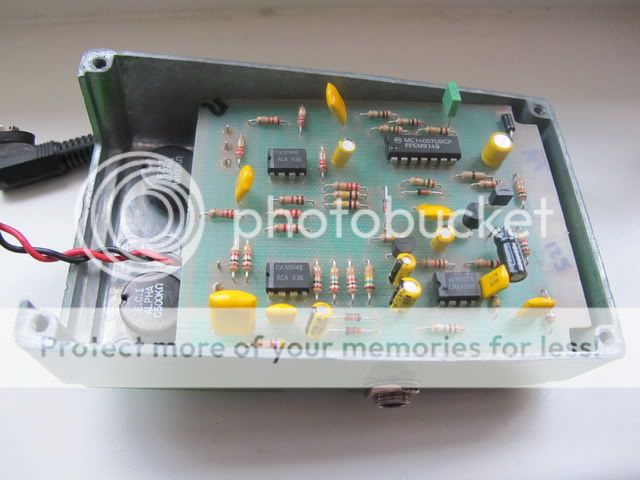
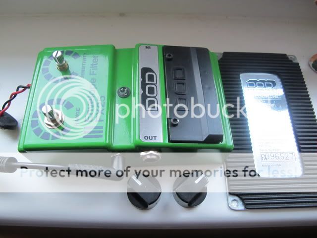
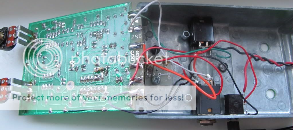
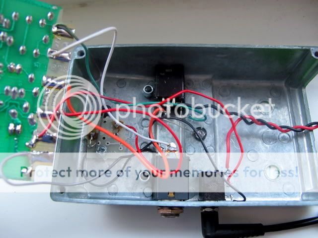
I have a DOD FX25,the model made after this one.I was wondering what the resistor tacked on the back of the PCB was for?czech-one-2 wrote:Hi folks, I am placing a call for help! I have an early DOD FX-25. I bought it as a project but am requesting a photo or two of the wiring if anybody has one of these.When I received it it would NOT switch on or off, so I replaced the footswitch and still no luck.Then I replaced the 14007 ic and it is switching fine.However there is no output when on,only when off.The wiring had been re-done when i bought it so I'm feeling there is a good possibility that maybe something is screwy there. The wires and connections are solid,but being that they arent original I suspect there may be a problem there.The circuit protection diodes are fine,and I tried piggybacking the two ca3094 chips with ca3080's and the lm1458 with another lm1458 to no avail,so I dont beleive its the ic's either.I changed the 47uf electrolytic,and installed a blue led as the original was blown, but I'm at a loss for what the problem is.
Any suggestions or photos would be greatly appreciated! Obviously this pedal was damaged early in its life,cause it doesnt have a scratch on it,came in the original box,and had a blown 14007 switching ic.
Thanks in advance! B
[ Image ]
[ Image ]
[ Image ]
[ Image ]
Information
- Posts: 1
- Joined: 02 Dec 2014, 10:07
Same problem. Hope someone can give a hand.soupbone wrote:I have a DOD FX25,the model made after this one.I was wondering what the resistor tacked on the back of the PCB was for?czech-one-2 wrote:Hi folks, I am placing a call for help! I have an early DOD FX-25. I bought it as a project but am requesting a photo or two of the wiring if anybody has one of these.When I received it it would NOT switch on or off, so I replaced the footswitch and still no luck.Then I replaced the 14007 ic and it is switching fine.However there is no output when on,only when off.The wiring had been re-done when i bought it so I'm feeling there is a good possibility that maybe something is screwy there. The wires and connections are solid,but being that they arent original I suspect there may be a problem there.The circuit protection diodes are fine,and I tried piggybacking the two ca3094 chips with ca3080's and the lm1458 with another lm1458 to no avail,so I dont beleive its the ic's either.I changed the 47uf electrolytic,and installed a blue led as the original was blown, but I'm at a loss for what the problem is.
Any suggestions or photos would be greatly appreciated! Obviously this pedal was damaged early in its life,cause it doesnt have a scratch on it,came in the original box,and had a blown 14007 switching ic.
Thanks in advance! B
[ Image ]
[ Image ]
[ Image ]
[ Image ]
-
astrobass

- Cap Cooler
The momentary switches in DOD stomps aren't great, but they're just normal momentary SPST buttons. You can get a bag of 25 for $1 probably on ebay that will be of at least the same quality and get a good five years or more out of one.
Also if you email them with a serial number, they'll give you the factory schematics if they have them. I've received schematics for like four different DOD pedals that way. The factory schematics are quite good too, they're PDFs and are totally legible.
Also if you email them with a serial number, they'll give you the factory schematics if they have them. I've received schematics for like four different DOD pedals that way. The factory schematics are quite good too, they're PDFs and are totally legible.
I made a short blog post about doing the filter output mod, to change the output from bandpass to lowpass or make it switchable, take a look at it here:
http://tubehead123.blogspot.com/2015/01 ... wpass.html
http://tubehead123.blogspot.com/2015/01 ... wpass.html
-
ppluis0

- Diode Debunker
Hi Piod,piod wrote:Here is sound https://dl.dropboxusercontent.com/u/209 ... odfx25.mp3 And my tweaked layout for bass with blend. But I have a one trifle: when we add decay knob, it's work good, but bias voltage on cap is drop down (when we tune this knob). Bias need to be 0,9v on electrolytic cap for a clean first attack. I don't have time for resolve it. (Adding 470-1k attack resistor don't resolve it) Solution is find way to have and hold starting bias voltage on 0,9v then cap will charge to 2,5v. Please comment if you have suggestions.
Try the following solution:
Lift the negative terminal of capacitor C11 from ground.
Make a string with three germanium diodes (or schottky diodes) connected in series, with the first anode soldered to the previously released capacitor terminal, and the last cathode connected to ground.
Connect a resistor, say 100K, from VB to the junction of the negative side of the cap, and the first diode in the series.
This way you have 0.9 Vdc appearing in these three diodes, and have lifted the same amount on the positive side of that electrolytic.
Hope this solve your problem. Please keep us posted about the result of this experiment.
Cheers,
Jose
-
Mbas974
- Resistor Ronker
Hi all, I'm very happy with my pedal I built some time ago, everything is working well.
One question related to this circuit but O.T.
Will it be possible tweak the circuit in order to not have the envelop ?
Let me explain... this pedal is extremely silent that only when I play sound come out... in other words it is a GREAT GATE pedal.
So I was wondering whether I can mod it to change it in a standard GATE without the envelop.
...hope it is clear.