Page 2 of 6
Re: DOD - FX25 ( Envelope Filter )
Posted: 08 Dec 2010, 17:34
by czech-one-2
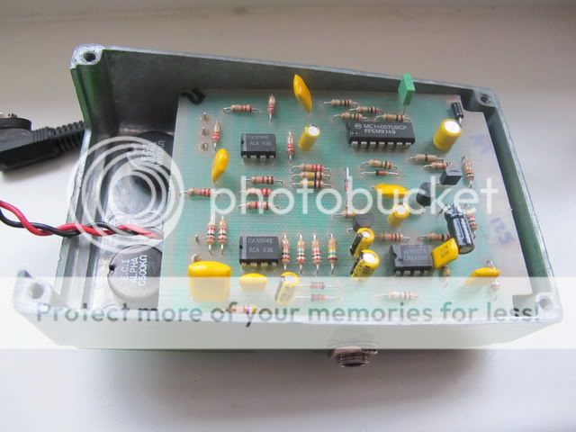
Hi, I just picked up an old lime green FX-25 . However all of the wires to the board are un-attached,and even a couple jack wires are off. I knew this was going to be a project but it looks like I need some assistance.Does anybody have one of these that they could take apart,pull the board out and take a couple photos of the wireing?
I would be eternally gratefull!
1st edition DOD FX-25 envelope filter, help/pics needed!
Posted: 09 Dec 2010, 14:49
by czech-one-2
Hi folks, I am placing a call for help! I have an early DOD FX-25. I bought it as a project but am requesting a photo or two of the wiring if anybody has one of these.When I received it it would NOT switch on or off, so I replaced the footswitch and still no luck.Then I replaced the 14007 ic and it is switching fine.However there is no output when on,only when off.The wiring had been re-done when i bought it so I'm feeling there is a good possibility that maybe something is screwy there. The wires and connections are solid,but being that they arent original I suspect there may be a problem there.The circuit protection diodes are fine,and I tried piggybacking the two ca3094 chips with ca3080's and the lm1458 with another lm1458 to no avail,so I dont beleive its the ic's either.I changed the 47uf electrolytic,and installed a blue led as the original was blown, but I'm at a loss for what the problem is.
Any suggestions or photos would be greatly appreciated! Obviously this pedal was damaged early in its life,cause it doesnt have a scratch on it,came in the original box,and had a blown 14007 switching ic.
Thanks in advance! BK
Re: DOD - FX25 ( Envelope Filter )
Posted: 09 Dec 2010, 15:31
by borislavgajic
Post some pictures of your pedal...PCB both sides please, and someone will help.....

Boris
Re: 1st edition DOD FX-25 envelope filter, help/pics needed!
Posted: 09 Dec 2010, 15:58
by MarcoMike
beautiful pedal... I never find such a project-deal... anyway, try to audio probe the signal and see where it stops... schematic available on the internet, on topopiccione.com for sure
Re: 1st edition DOD FX-25 envelope filter, help/pics needed!
Posted: 09 Dec 2010, 19:45
by czech-one-2
MarcoMike wrote:beautiful pedal... I never find such a project-deal... anyway, try to audio probe the signal and see where it stops... schematic available on the internet, on topopiccione.com for sure
Hi and thanks for the reply.I have the schematic but no audio probe.I'm really hoping for a photo to see if the wiring was done correctly.I had a hunch that the switching problem was the 14007 chip,and since my dod compressor had one I swapped them out and it works! Maybe I should try to use an audio probe again,but the last time was a miserable failure.Everything I touched sounded the same through my amp,and I eventually gave up.
I'd even be willing to send it to somebody [in Europe] on this forum more qualified than me to fix it

Cause I really want this on my pedalboard!
Any suggestions,hunches or photos are appreciated!!
Re: DOD - FX25 ( Envelope Filter )
Posted: 09 Dec 2010, 19:54
by czech-one-2
borislavgajic wrote:Post some pictures of your pedal...PCB both sides please, and someone will help.....
Boris
Thanks Boris,I just did over on the 'Request Folder' sub-forum.
Wish me luck!
Re: 1st edition DOD FX-25 envelope filter, help/pics needed!
Posted: 09 Dec 2010, 21:11
by czech-one-2
So cool, the audio probe is working! I found a 100k resistor in the input that has signal on one end,but not the other ....could be the culprit [I hope!]
Re: 1st edition DOD FX-25 envelope filter, help/pics needed!
Posted: 09 Dec 2010, 22:21
by czech-one-2
well,the resistor needed replacing,but still no auto wah

With the audio probe I'm getting nothing from Q2 which is marked j113. Thats a j201?
heres a schematic,but its a later model I beleive...

Re: 1st edition DOD FX-25 envelope filter, help/pics needed!
Posted: 09 Dec 2010, 23:46
by MarcoMike
if you don't get any signal past Q2 it means the switching system is not working: either Q2 is fried, or the control voltage does not arrive on it... so look in that direction.
or short Q2 (bypass it connecting drain to source)... you should hear something going on...
and... which 100k resistor were you referring to??? there should be no signal going through any 100k resistor...
nowI notice this is the request folder... should we go on here?!
Re: 1st edition DOD FX-25 envelope filter, help/pics needed!
Posted: 09 Dec 2010, 23:56
by czech-one-2
MarcoMike wrote:if you don't get any signal past Q2 it means the switching system is not working: either Q2 is fried, or the control voltage does not arrive on it... so look in that direction.
or short Q2 (bypass it connecting drain to source)... you should hear something going on...
and... which 100k resistor were you referring to??? there should be no signal going through any 100k resistor...
nowI notice this is the request folder... should we go on here?!
OOps, I suppose there is a better place to request help. Maybe the moderators can move this to a more visible forum?
If not I will start it over again tommarow. I'll check out Q2 again then as well.And the 100k was r6 I suppose,so that should not be audible with the probe?
Re: 1st edition DOD FX-25 envelope filter, help/pics needed!
Posted: 10 Dec 2010, 00:28
by MarcoMike
yes, no audio past R6... it's there to set the reference voltage...
DOD FX-25 rev -A gut shots / opinions needed!
Posted: 10 Dec 2010, 10:16
by czech-one-2
Hi folks, I am placing a call for help! I posted this in the 'Requests folder' by mistake

,hopefully more people will see it here! I have an early DOD FX-25. I bought it as a project but am requesting a photo or two of the wiring if anybody has one of these.When I received it it would NOT switch on or off, so I replaced the footswitch and still no luck.Then I replaced the 14007 ic and it is switching fine.However there is no output when on,only when off.The wiring had been re-done when i bought it so I'm feeling there is a good possibility that maybe something is screwy there. The wires and connections are solid,but being that they arent original I suspect there may be a problem there.The circuit protection diodes are fine,and I tried piggybacking the two ca3094 chips with ca3080's and the lm1458 with another lm1458 to no avail,so I dont beleive its the ic's either.Ireflowed the solder joints,and inspected them all for bridges or cold joints.I changed a 47uf electrolytic,and installed a blue led as the original was blown, but I'm at a loss for what the problem is. The original owner said he bought it as a repair from a closing music shop.Obviously this pedal was damaged early in its life,cause it doesnt have a scratch on it,came in the original box,and had a blown 14007 switching ic,so somebody probably used the wrong adapter.
I'm still kind of a newb at this, but I'm determined to get this one working! Just made an audio probe and I'm getting nothing from Q2, so that may be my next component swap.Only it is a j111, maybe a j201 would work? But first,any photos of the wiring would be greatly appreciated!
Thanks in advance! BK
Re:
Posted: 10 Dec 2010, 12:30
by DoctorSound
soulsonic wrote:Which one is that? I have a handful of older DOD pedals.
I hope that schematic may help you
Re: 1st edition DOD FX-25 envelope filter, help/pics needed!
Posted: 10 Dec 2010, 12:42
by borislavgajic
That 100K resistor is at the output....not input...so if you have swapped in and out jacks....? no sound
Boris
Re: 1st edition DOD FX-25 envelope filter, help/pics needed!
Posted: 10 Dec 2010, 15:00
by MarcoMike
well, there should be no bypass either... I guess that's not the case...
Re: DOD FX-25 rev -A gut shots / opinions needed!
Posted: 10 Dec 2010, 15:55
by czech-one-2
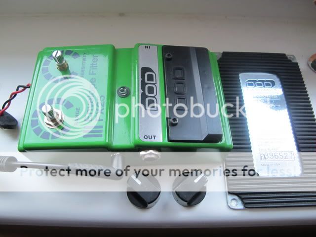
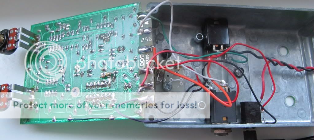
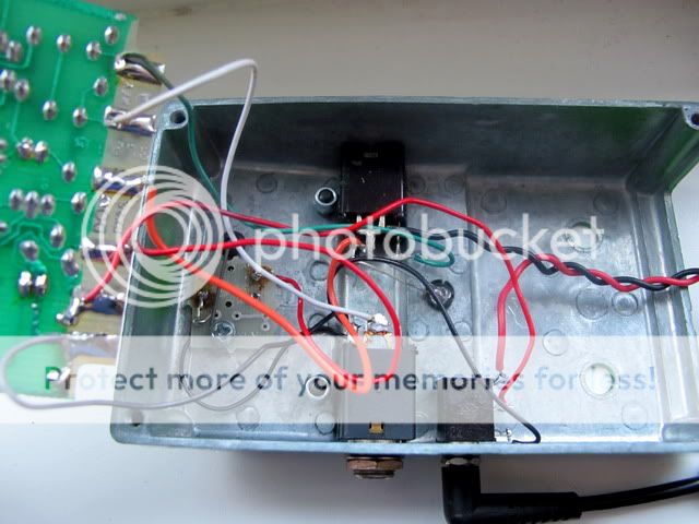
OK........ it now looks like I did have a couple bad diodes ,D-1 and D-2,upon replacement I'm now getting audio from the probe along the entire input,with no bad resistors,caps,diodes or Ic's. So now If anybody out there has one of these I really need a photo of the wiring.
I'm 90% sure thats where the problem is.
I'll buy you a round if you ever come to Prague!

Re: DOD FX-25 rev -A gut shots / opinions needed!
Posted: 10 Dec 2010, 16:24
by borislavgajic
I must say nice looking pedall......and nice sharp photos....but please post photos not from angle.......it is easyer to see it from 90 degree angle.....
thanks
Boris
Re: DOD FX-25 rev -A gut shots / opinions needed!
Posted: 10 Dec 2010, 17:36
by czech-one-2
Ok,I'll try to get some pics on saturday.
I replaced and socketed the 1458 chip and now I'm getting a faint distorted sound when on,but I'm still stumped.....

Re: DOD FX-25 rev -A gut shots / opinions needed!
Posted: 10 Dec 2010, 19:36
by MarcoMike
wiring shouldn't be that complicated: everything is on-board, jacks are ok, as you get signal trhrough... the only thing is the switch, maybe try to disconnect it and activate it manually, shorting (momentarily) the 2 wires together, and if you have already some sound passing past Q2, the switch is fine, check input and output pins of each CA chip... then if that's ok go further to the last op amp... move the knobs to high sens so you're sure signal is not "low passing" too much...
Re: 1st edition DOD FX-25 envelope filter, help/pics needed!
Posted: 10 Dec 2010, 19:48
by andrewkirsanow
I would agree that this does sound like maybe the FET switching around Q2 could be to blame, the JFET itself could be fried. Did you try shorting from Source to Drain on Q2 to see if there was any difference?
Have you checked for signal at Pin 4 of U2 with the effect activated??
The only thing I'd want to really comment on is that piggybacking ICs in circuit really isn't a reliable way to check for a failed IC. For example, if a short has developed inside the IC (as can happen frequently), and it shorts the audio signal path to ground, then a piggybacked IC would make no difference at all. Add to that that putting two healthy ICs in parallel like that can actually cause the circuit to fail anyway! The only reliable way to verify the ICs is to either verify that all the other components around them are OK and connected properly, thus indicating that the IC has failed, or remove and replace. Even then, there is always the possibility that the replacement part is either faulty from new, or gets damaged during the soldering!