Page 2 of 2
Re: Ross Distortion
Posted: 14 Jul 2010, 14:50
by snmavronis
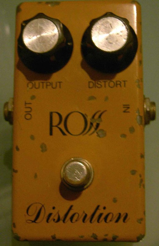
I'm curious about my particular Ross R50 Distortion variant since no schematic I've see shows the polarity protection diode and it's unusual to see a tan model made in Taiwan, which are all supposed to be in black boxes. The basic circuits of the Ross Distortion, MXR Distortion+, and gray DOD 250 Overdrive are very similar. As a matter of fact the first Ross Distortions were a dead ringer to the MXR Distortion+ (see image below) complete with exact same PCB layout and script font labeling housed in the same Bud enclosure! It sounds like there was a lot of 'cloning' going on even back then between the pedal companies! So what was the historical order of these 3 pedals - 1. MXR, 2. Ross, 3. DOD?
I'll add the Ross to my pedal chain with my 250 clone and toggle between them later to compare, but by themselves they do almost sound the same. Although surprisingly for a distortion pedal the level output seems to be less as loud in the Ross than the 250 probably from the different level pots used? IDK...
I still want to make photo-exact graphics of all 3 PCB layouts. I'll probably have to draw all 3 'by hand' using GIMP or something. Even though Peps1 made a very very nice copy of the 250 PCB already, it isn't 100% exactly "photo matched" in some small areas and slight angled positions of parts. But it is at least in the upper 90 percentile accurate and probably about as close as you can get to the real thing! We guesstimated the PCB size too while he was researching photos that I helped provide as reference. I'd like to verify the exact board dimensions measured from the real thing though instead of guessing based on skewed and distorted photographs. I'll check with my sources again and request that.
Re: Ross Distortion
Posted: 14 Jul 2010, 19:07
by mictester
JOHNO wrote:snmavronis wrote:I noticed on that page you linked the photo shows larger CTS pots from 1978 and only 2 diodes. I guess after then compared to my picture they used 3 diodes and different 16mm pots
Looking at the schematics at the home wrecker site I noticed the black version has three diodes for asymetrical clipping but, there is no reverse polarity diode drawn on the schematic. In the tan version there are two diodes for symetrical clipping but, no reverse polarity diode drawn on the schematic. But I can't find any gut shot's from a black version to confirm that it had three diodes for clipping. In the pic's I can find one version had two diode and the other had three diodes but one of those diodes was for polarity protection. Maybe there is an error in the schematic? Anyone have any further information?
The published circuit for the black version is wrong! It uses just two silicon diodes for the clipping. The third one is for the reverse polarity protection. As usual it uses the cheapest parts available, and is nothing special at all!
ross distortion...how could i screw this up? [schematic]
Posted: 14 Oct 2012, 19:39
by pinkjimiphoton
so...used to have one of those tan ross distortions. always liked it, but had sold it or bartered for a satchel or something, i dunno, years ago.
so i figured..nothing to it, figured would give me something to do while shirking some other responsibility.
so i found this here schematic, which is supposed to be verified...

and figured, ok, let's work up a vero... so i did. this is it.

but...it don't work. i can kind of get it to work, but that's only an annoying oscillating howl...the distortion pot does nothing (and am i right that on the schematic the jumper should be towards the +, not ground?) at all, and i'm getting weird voltages i'm not expecting.
pin 1 4.12
2 4.17
3 3.61
4 0
5 0
6 8.0
7 8.0
8 8.28
i've tried a lot of different chips, some motorboat, some oscillate at bug pitch.
if i pull the dang chip, it passes audio. wtf? :icon_eek:
i've looked this thing over, traced it thru point by point, as far as my simple brain can see, it matches the schematic..
is the schem wrong maybe? anyone else built one of these?
thanks!
Re: ross distortion...how could i screw this up?
Posted: 14 Oct 2012, 21:47
by Biochemist
Tagboard effects (IvI) has a nice vero layout of this and if I'm not mistaking, it's supposed to be verified. Might be worth it to compare yours with his... just a thought...
Re: ross distortion...how could i screw this up?
Posted: 14 Oct 2012, 22:22
by Duckman
Mr. Pink, your vero is consistent with your schemo, so, if that schemo is correct, recheck your build. First, your power source, if it's ok, then you have something bridged/misconnected there.
Re: ross distortion...how could i screw this up?
Posted: 14 Oct 2012, 22:51
by cpm
I'd lower the divider resistors from 1M to 100k or 10k... and connect the opamp ground to the lower strip, for a shorter path to Gnd
Also, the unused opamp looks to be latching to the rails, connect the input to Vref, instead of gnd
those changes should add some stability, just in case
Re: ross distortion...how could i screw this up?
Posted: 15 Oct 2012, 12:30
by DrNomis
I noticed that C7 is 10nF, C7 is the supply bypassing capacitor and 10nF is too small a value, it should be anything from 10uF to 470uF for it to do an effective job at supply bypassing, it's probably one of the reasons why your vero build is oscillating pinkjimiphoton, hope that fixes it.....

And, I'd also make the two 1M divider resistors 10k or 22k as well....
Re: ross distortion...how could i screw this up?
Posted: 15 Oct 2012, 16:28
by pinkjimiphoton
thanks brothers,
i too thought this schem looked a little dicey, but it matches all the others i've found.
at the suggestion of you guys, and the guys on the other forum, i've taken the liberty to make some changes...
i am gonna try and change c7, but if that doesn't work, am scrapping the whole project and re-doing it.
i've done another layout with the changes i'm making, and will post it when i'm done if it works out.
it MAY be a problem with the chips, too... some of these gave me similar problems on another cct recently, they could be cooked and i don't know about it.
onwards and upwards..
Re: ross distortion...how could i screw this up?
Posted: 15 Oct 2012, 19:46
by DrNomis
A good idea is to solder an 8-pin IC socket into place on the board rather than solder the IC in place, saves having to de-solder the IC if it proves to be faulty.....
An 8-Pin IC socket also protects the IC from heat damage too...
Hope the new board works.....
Re: ross distortion...how could i screw this up?
Posted: 15 Oct 2012, 21:37
by pinkjimiphoton
alright.... as it turned out, there were multiple problems... the unused side of the chip was oscillating, and that was making everything nuts.
i tried tieing pin 5 to vref, no dice. ended up shorting pins 4,5,6 and 7 together.
now we had some output, bit still no distortion.
so i worked my way back from the pot, and tested everything. turned out to be bad solder on the 1m resistor between 1 and 2. fixed it. gain pot was achieved.

tried a 50k gain pot...sounded pretty good, but went with the original.
i swapped out c4,c6 and c7, added one more cap (to help nuke the maggots chewing in your ears way up high noise) and a transient protection resistor. also added reverse polarity diode.
this thing is freekin SWEET. i tried every opamp i had, and some sounded killer, some not so much. my favorite was the 1458, but in the end, it was lacking a little body in the mids...so i tried stacking a tl072 on top of it, in parallel.
i LOVE IT. sounds just like the distortion i remember from my youth..stacking the opamps gave it a slightly different charachter, but i like it...stupid pedal trick to come soon.
the best part? i fit it all on the original board with a couple minor modifications. (yes, i socketed the chip, always do)
so...verified...here ya go, Ross Da Boss...the minor reworking of the Ross Distortion (the tan one)

Re: Ross Distortion
Posted: 15 May 2018, 03:49
by romdos
I know it's been 8 years, but I just saw your post and I have a black ross from 1981. I'd be willing to send you pics if you still want them.
Re: Ross Distortion
Posted: 18 May 2018, 14:23
by rs
Please do post them.