Capacitor locations are not the same in vintage unitroseblood11 wrote:The circuit is very similar to the newer versions. Try to do the mods that I described above - it´s really a great improvement!
Corrections to fit in the vintage unit as fallows:roseblood11 wrote:
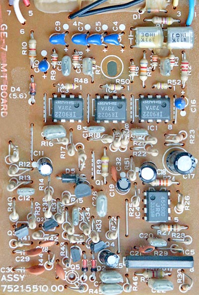
-replace capacitors:
C18,C25, C29, C30 : 0.047 µF
C21, C22, C32 : 1 µF
C13 : 0.1 µF
(use stacked metal film caps (MKT) for all positions!!! Panasonic ECQ-V series sounds very good here)
C22, C23, C24, C26 : .047uF
C11, C19, C25 (electrolytics) : 1uF
C13 : .1uF
All caps Panasonic ECQ-V all the way as you suggested and sounds great! Now time to play with tantalums and the filter caps - they just get bad/noisy with the age. I have some Sanyo Os-Con in the mail, so I'll use those for filtering, and Nichicons muse for the rest of electrolytics. Will see what does this changes
MartyM wrote: The problem was mostly the crap tantalum caps attached to each tone band.
Swopping them out for decent poly caps helps a LOT
Cheers
Pawel


