Alright, thank you!
This is the result:
U1:
Pin 1: 7.40 V
Pin 2: .503 V
Pin 3: 1.465 V
Pin 4: 00.5 mV
Pin 5: 1.485 V
Pin 6: 4.77 V
Pin 7: 1.92 V
Pin 8: 8.07 V
U2:
Pin 1: 00.4 mV
Pin 2: 00.4 mV
Pin 3: 00.4 mV
Pin 4: 00.0 mV
Pin 5: 00.2 mV
Pin 6: 00.2 mV
Pin 7: 00.2 mV
Pin 8: 00.3 mV
Tycobrahe - Parapedal [schematic]
-
JimSalabim

- Breadboard Brother
-
armdnrdy1
- Breadboard Brother
It looks like U2 isn't getting power.
I double checked your soldering....it "looks" ok.
Pull the ICs and check for continuity from the socket on the component side to the trace side of the IC pins.
(Continuity one lead on socket side of IC pin, the other lead on trace side of corresponding IC pin. Meter mode switched all the way to the right. Looks like your meter should make a sound when the two leads are touched together. (continuity)
If everything checks out OK...then check the voltages again...same thing pin by pin and then post.
-
JimSalabim
- Breadboard Brother
The socket connections are fine.
But the voltages are still near 0, now also on the first IC!
But the voltages are still near 0, now also on the first IC!
-
JimSalabim
- Breadboard Brother
Yes, same thing! No voltage at all pins.
-
armdnrdy1
- Breadboard Brother
Two things...
You have a cold solder joint somewhere in the power or ground path possibly one of the jumpers. Check all solder joints...even off board hardware...ie: DC jack and input jack.
Where sis you get the component parts list that corresponds with the layout?
I don't see a negative ground schematic.
You have a cold solder joint somewhere in the power or ground path possibly one of the jumpers. Check all solder joints...even off board hardware...ie: DC jack and input jack.
Where sis you get the component parts list that corresponds with the layout?
I don't see a negative ground schematic.
-
JimSalabim
- Breadboard Brother
OK, I’m checking all solder joints again (I already checked the continuity of everything right after soldering).
I used the parts from this GIF (second schematic)
http://www.geofex.com/FX_images/parapedal.gif
and the second layout from the PDF:
http://www.geofex.com/FX_images/newparapedal.pdf
I know the GIF shows a positive ground schematic, but the PDF shows a negative ground layout (at least that’s what it says). And the component parts should be the same?!
I put in the elkos and the diode in the direction of the PDF (second layout).
I used this wiring for true bypass:
-
armdnrdy1
- Breadboard Brother
At this point..I would hit all of the solder connections again.
There is a loose/bad connection somewhere which is the cause of the original problem...not working, no power to U2, and then no power to both ICs.
There is a loose/bad connection somewhere which is the cause of the original problem...not working, no power to U2, and then no power to both ICs.
-
JimSalabim
- Breadboard Brother
The problem must be somewhere else. I just tried two different diodes (a 1N4001 and another one which I can’t identify) and with both there’s voltage on every pin (except on the pins which lead to the ground). But still no sound. One time just hum, the other time nothing at all.
-
JimSalabim
- Breadboard Brother
Maybe it’s correct that the layout says "D2" instead of "D1" and I just need a completely different diode? But which one would this be?
But since I don’t know anything about diodes, this assumption could also be complete nonsense I don’t know …
But since I don’t know anything about diodes, this assumption could also be complete nonsense
-
JimSalabim
- Breadboard Brother
Update: Took a new 1N270 diode, now there’s voltage everywhere too:
U1:
Pin 1: 7.53 V
Pin 2: .510 V
Pin 3: 2.90 V
Pin 4: 00.5 mV
Pin 5: 2.89 V
Pin 6: 4.83 V
Pin 7: 1.94 V
Pin 8: 8.16 V
U2:
Pin 1: 6.32 V
Pin 2: 2.85 V
Pin 3: 2.89 V
Pin 4: 00.8 mV
Pin 5: 2.88 V
Pin 6: 2.81 V
Pin 7: 7.45 V
Pin 8: 8.14 V
Still no sound …
U1:
Pin 1: 7.53 V
Pin 2: .510 V
Pin 3: 2.90 V
Pin 4: 00.5 mV
Pin 5: 2.89 V
Pin 6: 4.83 V
Pin 7: 1.94 V
Pin 8: 8.16 V
U2:
Pin 1: 6.32 V
Pin 2: 2.85 V
Pin 3: 2.89 V
Pin 4: 00.8 mV
Pin 5: 2.88 V
Pin 6: 2.81 V
Pin 7: 7.45 V
Pin 8: 8.14 V
Still no sound …
-
armdnrdy1
- Breadboard Brother
Okay...
Those voltages look way better.
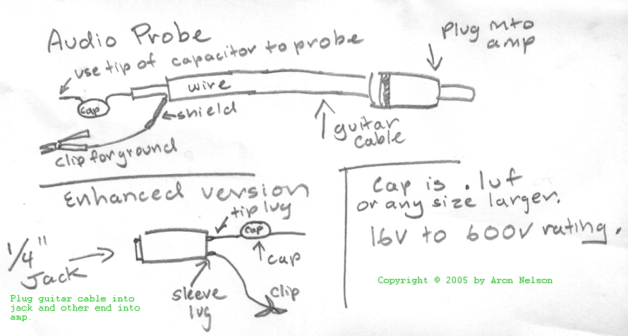
The best thing to do is use an audio probe to see where the signal stops.....then you will know what to target.
Here is the link for an audio probe:
https://www.diystompboxes.com/pedals/audioprobe.jpg
You have to build it. An old guitar cable and a capacitor is all you need.
Build this...and then I'll give you direction how tom use it.
Those voltages look way better.
The best thing to do is use an audio probe to see where the signal stops.....then you will know what to target.
Here is the link for an audio probe:
https://www.diystompboxes.com/pedals/audioprobe.jpg
You have to build it. An old guitar cable and a capacitor is all you need.
Build this...and then I'll give you direction how tom use it.
-
JimSalabim
- Breadboard Brother
OK, got it!
-
armdnrdy1
- Breadboard Brother
Plug the 1/4" jack of the audio probe into a guitar amplifier. (with the volume turned low)
Plug a guitar into the input jack of the Parapedal.
Connect the ground from the probe to the ground of the Parapedal.
Power up the Parapedal and engage the effect switch.
Follow the schematic through the audio path touching the leg or pin of each component while strumming the guitar.
Start at the input jack and work your way into the circuit
The guitar signal should pass through the effect input and be picked up by the probe and sent to your amp.
You will hear the guitar as long as the signal is getting through to that point.
If the signal stops...you have an idea of where to look for problems. (wrong value resistor, bad solder joint, etc)
-
Intripped

- Cap Cooler
jim, recheck resistors values, i've already spotted 3 wrong values from the pic you posted:
R14 sould be 1M, not 1k
R4 should be 1k, not 1M
R15 should be 1M, not 1k
R14 sould be 1M, not 1k
R4 should be 1k, not 1M
R15 should be 1M, not 1k
-
JimSalabim
- Breadboard Brother
Thanks! I plugged an iPod to the input jack instead of the guitar.
The following picture shows the result. This is the result of a test with the "unknown" diode again - the 1N270 stopped working again as soon as I started testing. So the signal could not pass the opamp anymore. Before the opamp it was the same result with both diodes.
The signal was getting very low already at C1 (10nF), then even lower and especially with much hiss at the end of R2 (47K). Then behind U2 there was only very very low hiss. At all other points there was nothing.
-
JimSalabim
- Breadboard Brother
Green: good signal
Yellow: very low signal
Orange: very low signal with hiss
Red: Only hiss (very very low)
Yellow: very low signal
Orange: very low signal with hiss
Red: Only hiss (very very low)
-
JimSalabim
- Breadboard Brother
and it’s "behind U1" not "behind U2"