I would expect that R16 would connect directly to the power supply, not through R15. I haven't had a chance to download the photos to check this though.
I think the purpose of the of the power supply circuit is to have a soft start powerup, the voltage ramps up while C13 is being charged through a resistor -gives a thumpfree input jack plug-in...
What is the serial # of the unit? Is the Zip code 49001 or 49006?
...I love Jerusalem too
/M
In case you don't get it; The reason I'm asking for the serial number is because I'd like to try to put it on a timeline (not for some stupid reason like trying to claim ownership...). The reason that I'm asking for the Zip code (on the back of the pedal that is -not your zip code) is for the same purpose. The reference to Jerusalem is because your avatar is taken from the cover of the great Sleep (...High On Fire...Matt Pike....) album "Jerusalem" witch contains just one song 52 minutes long....
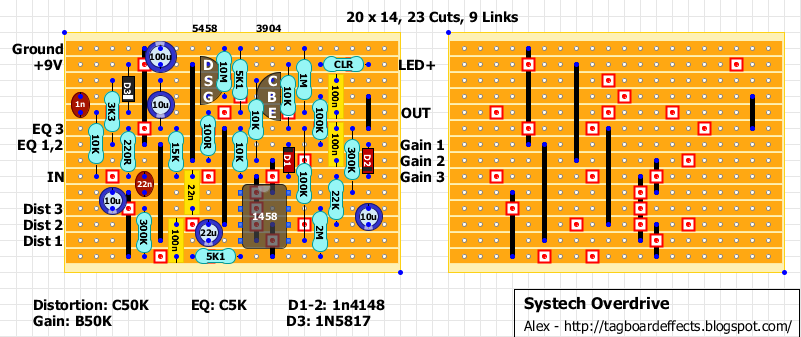
For anyone's info, both this schematic and this vero layout are verified. The layout is probably pretty poor as it's tight in some places and loos in others, but hey...it worked!
I did not look at the vero board layout, maybe you've corrected it there, but there are at least two errors in the schematic. R16 should connect directly to the +V buss and R4 should connect pin 5 to the +V/2 supply not pin 3. Pin 3 connects directly to the +V/2 bias supply.
Thanks! You're completely right, although as built it sounded close enough the original. Maybe I should A/B them again. Corrected Schem and Vero are here:
Thank you Doctor! A friend has the Harmonic Energizer and it's busted. I'm building him a clone on a Madbean board. He's a recording engineer for the last twenty years and after using his HE on most sessions involving any kind of rock guitar, became quite the Systech fan. Next, I'm going to build him this for Christmas and I couldn't have done it without your hard work here. It's going to be great! He knows these things exist but has never seen/heard one
Gonna go ahead and add my question here instead of starting a new thread, sorry for the zombie revive. I'm looking at building this with an optional expression pedal out jack for the EQ pot. Taking the leads from the EQ pot off the board and putting in a cliff style switching jack inbetween the board and the pot, it should be able to switch between the internal pot an an external pedal. My questions how to wire at the jack. Does EQ3 go to the ring, and then EQ1 go to tip and EQ2 sleeve? Or am I off there? Haven't built in expression outs to any pedal before, so apologies if it's a bit of a silly question.
I should think ring to EQ3 and tip to EQ1/2 should do it for most common expression pedals. The pot here is used as a variable resistor (5k, common exp. pedals are 10k), not a voltage divider like the gain and distortion controls so it only needs two connections.
btw the links to any schematic in this thread seem to be dead, but I found this one which seems to match the layout
oL941CZl.jpeg (21.77 KiB) Viewed 3225 times
modman wrote: ↑Let's hope it's not a hit, because soldering up the same pedal everyday, is a sad life. It's that same ole devilish double bind again...
Nocentelli wrote: ↑17 Sep 2020, 22:04
Welcome to FSB
I should think ring to EQ3 and tip to EQ1/2 should do it for most common expression pedals. The pot here is used as a variable resistor (5k, common exp. pedals are 10k), not a voltage divider like the gain and distortion controls so it only needs two connections.
btw the links to any schematic in this thread seem to be dead, but I found this one which seems to match the layout
oL941CZl.jpeg
Perfect! Thanks so much, that's exactly the info I was looking for, much appreciated. I was thinking of putting the whole thing into an old wah enclosure, but figure an expression out might be more useful overall.