Kind of Big Muff architecture, but with some weird fuckarounds
Starting on the input section and sustain pot two things are really odd to me:
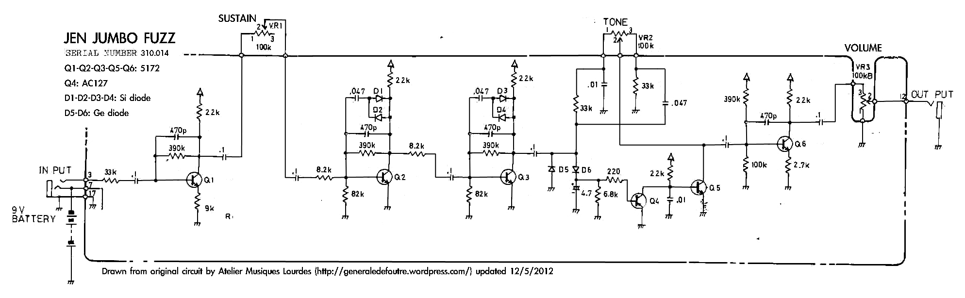
Schematic: http://generaledefoutre.files.wordpress ... shema1.jpg
Website it was taken from https://generaledefoutre.wordpress.com/ ... umbo_fuzz/
Picture of internals is attached, as there was some fucked ups with file extension
First of all there is no sustain pot limiting resistor to ground, and the sustain pot is wired other way around (probably schematic error)
There is no base to ground resistor on the Q1 as well, and AFAIK should be to, as it's a part of bias network/divider for input section
Could this be an error? Anyone have it to compare actual unit to schematic posted at ATELIER MUSIQUES LOURDES website
More fun is at tonestack
Vero coming soon, as soon as somebody justify schematic provided

