HS Shatterbox....corrected??? meet the scatterbox...
Posted: 15 Dec 2013, 04:35
an npn ge/si hybrid version of the shatterbox that actually works, sounds decent, and is useful...
with all due respect, and i KNOW that electric warrior traced an actual unit correctly, i built this unit, and frankly, as drawn i was completely unimpressed.... it was pretty useless as set up. so i took a good hard look at this circuit.
here is what i believe is actually what they intended, but screwed up back in the 60's.
this is built, verified, and working as expected.
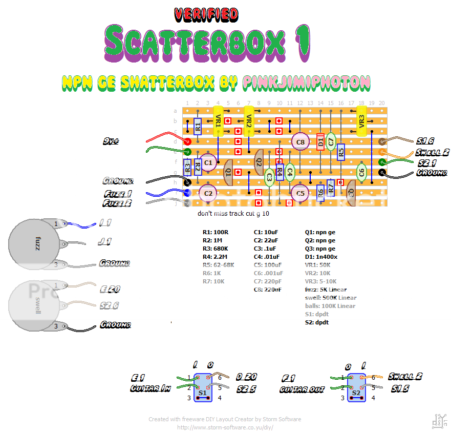
adjusting tr3 allows you to set the over all volume of the boost from below unity to pretty well above.
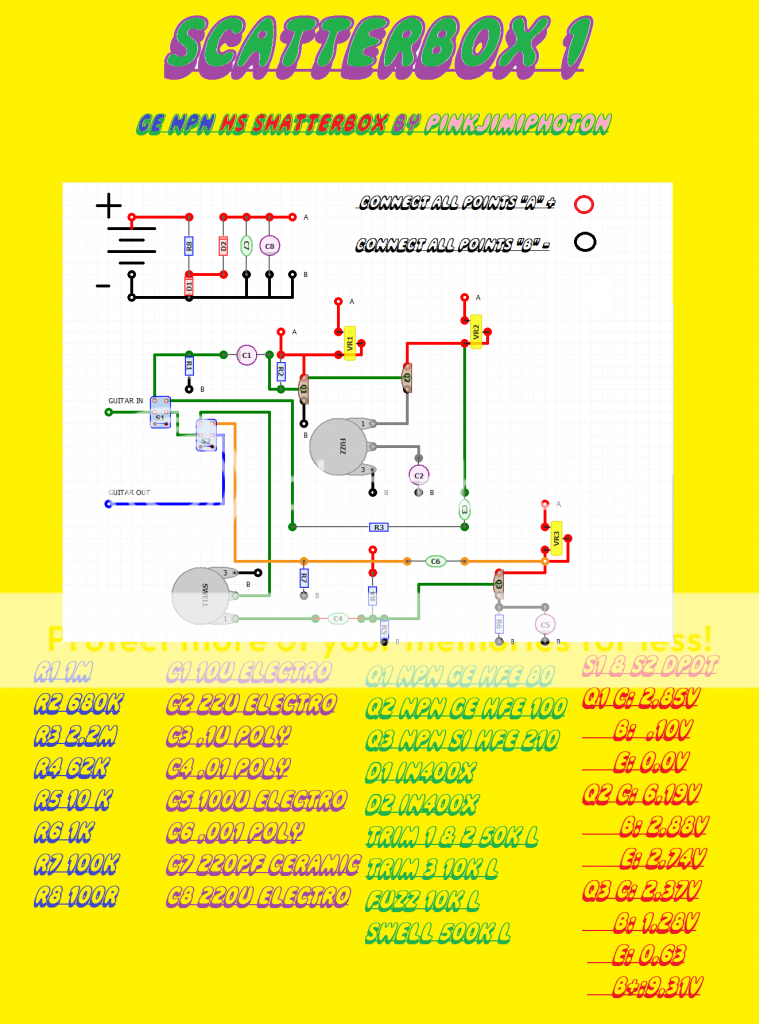
the actual transistors i used are in ge npn's from an old heathkit organ, house # r609980243,
q1 hfe 80, q2 hfe 90, and q3 is a bog standard 3904, hfe 210. a ge transistor in q3 gives more of a treble and distortion boost than volume boost.
the footswitch wiring is correct and modified to allow moving the pot to where i believe the proper position in the circuit should have been.
thanks to electric warrior for tracing an original, and leading to this possible discovery.
the one i built, once biased to the "sweet spots" for the transistors i used is a very nice dynamic fuzz, and a good solid boost completely independent.
by moving the swell control after the bypass switch, it's actually useful.
i believe this was the intention of the EE who developed this pedal.. you want a high inpedance input signal...2.2m is good and high.
by moving the 500k swell pot to the input node of the booster instead of the output node of the fuzz, i believe the 2.2m gives a high enough impedance to allow enough signal to get thru the switch, and hit at a high enough impedance at the input of the now moved swell pot to hit the booster section a lot harder... think of it like a tube amp, where you need a grid load resistor going to allow the tube to function.
i'm not savvy enough electronically to explain it any better than this, sorry.
all i can say is try it. moving that pot takes this thing from crappy relatively useless curiosity to an actually useable, toneful pedal that acts as you'd expect a fuzz into a boost to act.
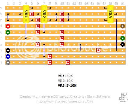
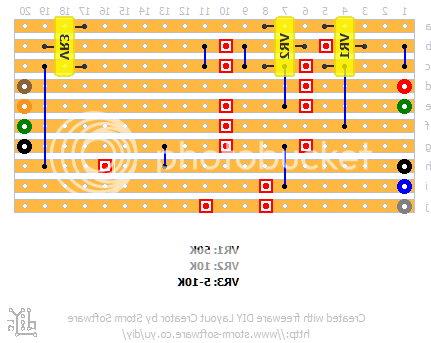
anyways... first attempt with DIYLC, not the best schem to be sure, but i am 100% sure it's right.
consider r7 as optional... i believe it was a dodge HS used to try and compensate for dropping the ball during the design process.
i can see no other reason why on earth anyone would bleed signal across the OUTPUT JACK with a 100k resistor!!
i tried it with and without.. it does smooth the signal just slightly. i wired it not across the jack, but the output node from the .001 cap.
anyways... schematic. stupid pedal trick video and updated veroboard layout to come soon.
peace.
pinkjimiphoton
with all due respect, and i KNOW that electric warrior traced an actual unit correctly, i built this unit, and frankly, as drawn i was completely unimpressed.... it was pretty useless as set up. so i took a good hard look at this circuit.
here is what i believe is actually what they intended, but screwed up back in the 60's.
this is built, verified, and working as expected.
adjusting tr3 allows you to set the over all volume of the boost from below unity to pretty well above.
the actual transistors i used are in ge npn's from an old heathkit organ, house # r609980243,
q1 hfe 80, q2 hfe 90, and q3 is a bog standard 3904, hfe 210. a ge transistor in q3 gives more of a treble and distortion boost than volume boost.
the footswitch wiring is correct and modified to allow moving the pot to where i believe the proper position in the circuit should have been.
thanks to electric warrior for tracing an original, and leading to this possible discovery.
the one i built, once biased to the "sweet spots" for the transistors i used is a very nice dynamic fuzz, and a good solid boost completely independent.
by moving the swell control after the bypass switch, it's actually useful.
i believe this was the intention of the EE who developed this pedal.. you want a high inpedance input signal...2.2m is good and high.
by moving the 500k swell pot to the input node of the booster instead of the output node of the fuzz, i believe the 2.2m gives a high enough impedance to allow enough signal to get thru the switch, and hit at a high enough impedance at the input of the now moved swell pot to hit the booster section a lot harder... think of it like a tube amp, where you need a grid load resistor going to allow the tube to function.
i'm not savvy enough electronically to explain it any better than this, sorry.
all i can say is try it. moving that pot takes this thing from crappy relatively useless curiosity to an actually useable, toneful pedal that acts as you'd expect a fuzz into a boost to act.
anyways... first attempt with DIYLC, not the best schem to be sure, but i am 100% sure it's right.
consider r7 as optional... i believe it was a dodge HS used to try and compensate for dropping the ball during the design process.
i can see no other reason why on earth anyone would bleed signal across the OUTPUT JACK with a 100k resistor!!
i tried it with and without.. it does smooth the signal just slightly. i wired it not across the jack, but the output node from the .001 cap.
anyways... schematic. stupid pedal trick video and updated veroboard layout to come soon.
peace.
pinkjimiphoton