Re: Maestro Brass Master request
by DavidRavenMoon » Sat Jan 03, 2009 4:29 pm
OK, I got it working!
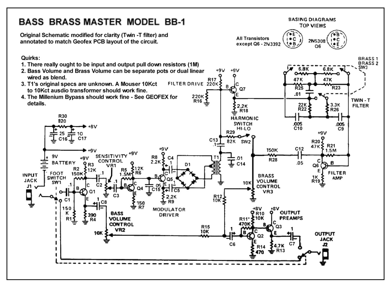
gtrgeek1 is correct... there seems to be nothing wrong with the original schematic (except for Q1's supply voltage being 8V and not 9V), and RG's PCB is correct.
So here's what I did... first there was the issue where on RG's layout sheet R22 and R27 are swapped. So I removed them and put them in the correct locations. That did little to help the Brass switch, but I at least heard something when I switched it. I had tried moving where R29 connected to C13, but I switched that back to the original location.
I decided to check Q6, since that was responsible for amplifying the output of the filter and sending it back to the circuit. I looked up the pin out for the Fairchild 2N5308.. voilà! I had it in backwards. It did match the layout as far as where the flat side was, but it had the emitter and collector swapped!
So I carefully unsoldered it and flipped it around.
Here's the results. First you hear the two settings of the Brass switch, then I flip the Harmonic switch, and then switch the Brass switch again. You go from very full to very thin, just like the real thing. The very thin setting is what Squire used a lot, as in the example I play from Close to the Edge, which has the dry signal mixed back in.
Brassmaster Fixed
I don't have a real one in front of me to compare, but going from memory, this is pretty much nails the tones I remember using.
Yay!
Re: Maestro Brass Master request
by R.G. » Sat Jan 03, 2009 10:24 pm
There's no matching to be done. They're all doing different jobs, so matching is superfluous.
I'm still kinda miffed that I just believed the pinout for the darlington that Maestro put on the schematic. Boy, talk about a silly beginner mistake to make. I know better than that and still didn't go look it up. That appears to be problem with any of these ever built.
The wringing-out exercise has resulted in simulating the entire mess, reworking and updating the original layout, and the (re)design of the function into an opamps-version that should be less temperamental and will have far fewer wires hanging off the board - I cold-switched the twin t filter.
More writing to do, but I'll put the whole mess on GEOFEX when I get it documented. David and Gtrgeek were absolutely instrumental in getting this done; I've never seen a Brassmaster in real life, so getting real, on-the-spot data helped filter out some of the hash.
R.G.
Re: Maestro Brass Master request
by rcubed » Sun Jan 04, 2009 12:22 am
Awesome. So by R.G., you mean R.G. Keen's layout dubbed the Brass Blaster, the PCB that General Guitar Gadgets sells? 'cause that is the one I have but have not soldered up yet. Are you using this layout:
http://www.generalguitargadgets.com/dia ... master.pdf ? If it's just Q6, then maybe R22 and R27 are correct?
rcubed
Re: Maestro Brass Master request
by DavidRavenMoon » Sun Jan 04, 2009 12:34 am
Yes, I bough the board from GGG. I'm using that layout in the link (geo_brassmaster.pdf). Install R27 where it's marked R22 (between R28 & C9) and install R22 between R26 & R18 where it's marked R27. If you look at the schematic you will see they are switched in the layout. The schematic is correct. I followed the traces on the board to verify this.
Check the 2N5308 you are using. The Fairchild part I used had to be installed with the flat side facing the left, which is the opposite of the layout. You want the emitter to be the top pin, and the collector to be the bottom. I neglected to check this before I installed it, and didn't think about it after.
DavidRavenMoon
Re: Maestro Brass Master request
by rcubed » Sun Jan 04, 2009 12:49 am
I just changed around Q6 and there it is. Everything works. I feel about calling the schematic wrong in terms of the diagramming of the circuit. Turns out the only wrong is the pinout of the 2N5308 on there with respect to the Fairchild parts we are using. Glad to finally get this all figured out. Thanks for all the help.
rcubed
Re: Maestro Brass Master request
by R.G. » Sun May 03, 2009 6:51 pm
controller700 wrote:I would prefer to use R.G.´s updated layout, but cannot find the PCB files for it! The PCB at GGG looks not the same as in R.G.´s new layout... any suggestions?
Same suggestion as by email. The board from GGG has been confirmed to produce correct sounding units when corrected with the two or three steps noted at GEOFEX. Those consist of
1. turn around the darlington 180 degrees. The factory schematic shows the incorrect pinout, and I correctly used the incorrect pinout.
2. two resistors are swapped.
3. I deliberately made the switching easier by changing switching between two resistors into paralleling two resistors. By actual builders comments, this produces little change, but by recalculating the resistors you can get *exactly* the same values as in the original.
No one has licensed the new layout, and I don't make PCBs to sell. If one of you wants to buy a license for making the new layout, cool. Contact me.


 [/quote]


