Sola Sound - Tone Bender Mark I (1965)  [schematic]

Discussion regarding early stompbox technology: 1960-1975 Please keep discussion focused and contribute what info you have...
User avatar
vanessa
Cap Cooler
Information
Posts: 466
Joined: 08 Jul 2007, 17:51
Been thanked: 10 times

Post by vanessa »

BIGSMITTY wrote:Will same ones for mkII circuit work? vanessa your the best.
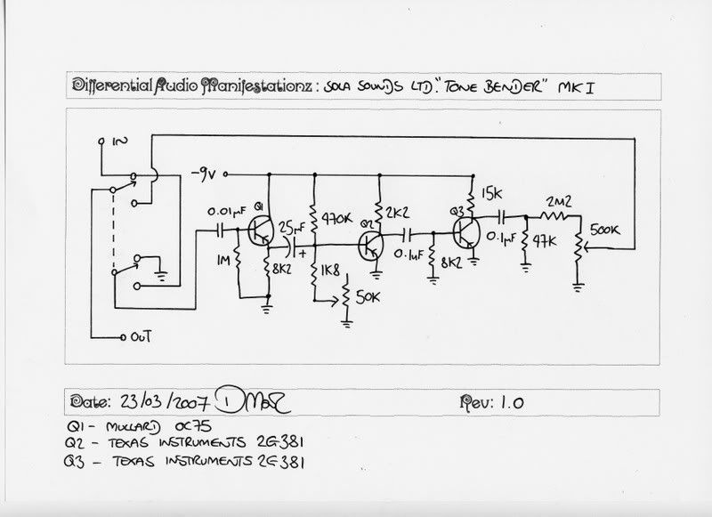
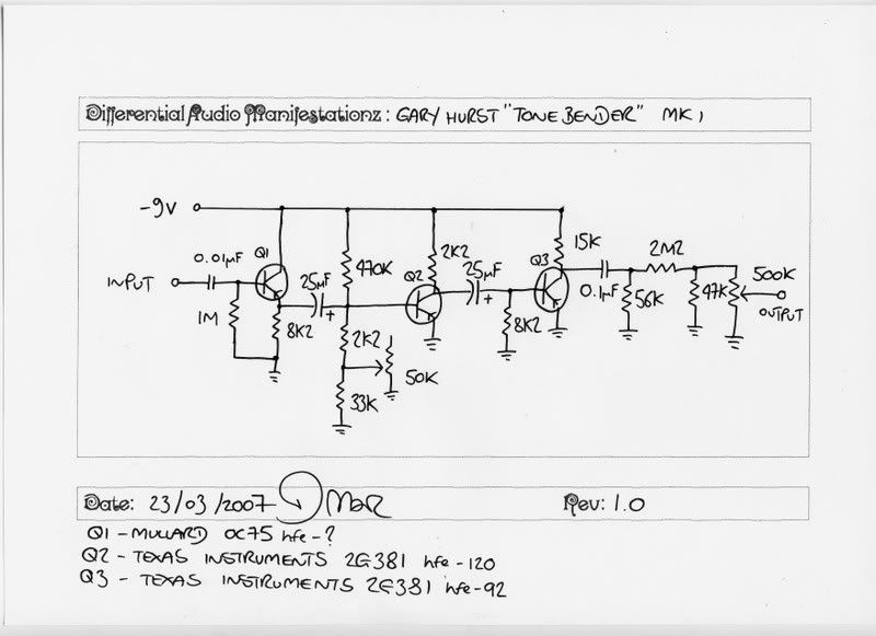
No, if you approach it that way it sounds too tight. You don't get the bee sting tone of the original. This pedal should sound like what you here on The Rolling Stones "Satisfaction" (the MKI was a Fuzztone clone, it is said Richards used a Fuzztone on this track) or better The Beatles "Think for Yourself" (it's possible they used the MKI on this track).
Read my earlier posts, it really needs a couple of low and leaky hfe (germaniums) in Q1, and Q3. Something like 40-60 in Q1. 80-100 in Q2, and 60-70 in Q3. But it gets weird from there. It needs them leaky here and there, and then there's tweaking the bias of Q2. I kind of see why Sola and Gibson stopped making these things. They must have had a lot of people complaining why they did not sound like Keith Richards or the Beatles and that might have ended in a lot of returns? Who knows? It's a bit of a pain in the rear to get that tone, but if you mess with it you can get it. I did.

User avatar
modman
a d m i n
Information
Posts: 4897
Joined: 19 Jun 2007, 16:57
Has thanked: 4410 times
Been thanked: 2139 times

Post by modman »

I found some

Tonebender Mark I pics and gut shots[/url]

Note the different types of transistors, and somehow I don't think these metal cans are original, looking at the soldering.
Please, support freestompboxes.org on Patreon for just 1 pcb per year! Or donate directly through PayPal

User avatar
vanessa
Cap Cooler
Information
Posts: 466
Joined: 08 Jul 2007, 17:51
Been thanked: 10 times

Post by vanessa »

modman wrote: Note the different types of transistors, and somehow I don't think these metal cans are original, looking at the soldering.
I was skeptical and thought I was sent on a wild goose chase, there was only one thing that AG caught from photos (a resistor value). Mine after a bit of tweaking sounds a pretty convincing clone of the original, so if there's been a switch-a-roo it has not changed the tone that much.

User avatar
JHS
Cap Cooler
Information
Posts: 483
Joined: 14 Jul 2007, 11:20
Been thanked: 5 times

Post by JHS »

The metal can trannies are original - 2x TI 2C381.
The other is a Mullard OC75.

JHS

User avatar
Solidhex
Resistor Ronker
Information
Posts: 261
Joined: 02 Apr 2008, 04:43
Has thanked: 10 times
Been thanked: 17 times

Post by Solidhex »

Sweet thread

Noticing the similarities between the MkI and the Maestro Fz-1 . Would there be anything to top me from putting say a 100k pot in series with the negative battery supply to sort of have a choice between the MkI's 9 volt supply and the Maestros 3 volt supply, or anywhere in between?

--Brad

User avatar
Solidhex
Resistor Ronker
Information
Posts: 261
Joined: 02 Apr 2008, 04:43
Has thanked: 10 times
Been thanked: 17 times

Post by Solidhex »

Yo

Well anyways, I tried it... this circuit is a bitch to bias. Without the correct transistors its hopeless. Lowering the power supply once its been biased just results in some wet fart noises.

--Brad

User avatar
JHS
Cap Cooler
Information
Posts: 483
Joined: 14 Jul 2007, 11:20
Been thanked: 5 times

Post by JHS »

You can drop the I-buffer.Trimpots are good for biasing different trannies.

JHS

User avatar
Solidhex
Resistor Ronker
Information
Posts: 261
Joined: 02 Apr 2008, 04:43
Has thanked: 10 times
Been thanked: 17 times

Post by Solidhex »

Yeah

Great info on Frank's site about all those circuits... http://www.guitar-pedals-effects.com/
Seems like if the input was connected directly to q2 in a non true-bypass situation it would get super loaded down by the fuzz pot going to ground he describes. Fine with me! One less transistor to tweak.
I had the basic circuit breadboarded so I switched values around. I had trimpots on the 1m, the buffer's emitter, and the resistor to ground from the base of the final transistor. They help but it seems without the right transistors and leakage its not a great sound. The Acetone Fuzz Master seems to be a more stable version of the circuit. Gotta try that too.

--Brad

User avatar
blanik
Solder Soldier
Information
Posts: 242
Joined: 04 Mar 2008, 17:10
Location: Montreal
Been thanked: 6 times

Post by blanik »

i just build a vero MkI and i can't get any of my transistors to work (got a bunch of SBE Ge generics, AC128s, 102s, etc...) all i get is a high pitched oscillation with some fuzzing in the background :-(

i'm pretty sure the circuit's values are made to bias properly the OC75 and two 2G381 but with all my transistors it doesn't work, according to the schem on the first page, what values should i play with to bias the whole thing and what value should i aim for on which pin of the GEs?

the schem on the first page is the most commonly seen but i found two variants involving a 33k resistor between the drive pot and ground, plus a resistor in parallel with the volume pot...

also interesting to note the 470k that's on all the schems was 180k on the original unit as noted earlier but the original tracer of the unit (the guy from D*A*M) substituted the 180k for a 470k to "make it easier to bias"?

from his site:
"The first schematic was traced from the 1965 MKI I had. The 470k should be 180K but I originally redrew this diagram for the "1965" and the 470k worked out better. It doesn't change the tone at all just makes the bias easier to do. The second schematic is from the MKI I repaired for geefuzz. It wasn't screened printed and did not state that it was a Sola Sound pedal so would have been a few months younger than the Sola Sounds Ltd model. Sola Sound Ltd MKI "
Image

Image

i'm curious about this next schem, just found it, different transistor numbers and some values? is this a modern "sound alike" with available parts and biased accordingly??
Image

User avatar
leeyoungun
Information
Posts: 10
Joined: 25 Dec 2008, 00:17

Post by leeyoungun »

blanik wrote:i just build a vero MkI and i can't get any of my transistors to work (got a bunch of SBE Ge generics, AC128s, 102s, etc...) all i get is a high pitched oscillation with some fuzzing in the background :-(
What's the gain and leakages measure out to? Sounds like too much leakage. I had the same problem until I found transistors with fairly low leakage.

User avatar
sonicvi
Solder Soldier
Information
Posts: 160
Joined: 30 Dec 2007, 07:17
Been thanked: 8 times

Post by sonicvi »

I used an OC75, OC71, and CV7003. Gains around 65,95, and 90 respectively, none with more than about 250uA leakage and it sounds like this.
http://homepage.mac.com/sonicvi/mk1clone.mp3
and my build
Image

User avatar
blanik
Solder Soldier
Information
Posts: 242
Joined: 04 Mar 2008, 17:10
Location: Montreal
Been thanked: 6 times

Post by blanik »

did you guys leave the 470k or used the "stock" 180k?

nice clip sonicvi, that's exactly the sound i want, i prefer this sound to the MkII sound...

R

User avatar
leeyoungun
Information
Posts: 10
Joined: 25 Dec 2008, 00:17

Post by leeyoungun »

I used the 470K. I followed the Sola Sound Ltd. schematic but went with different bias resistor values.

User avatar
leeyoungun
Information
Posts: 10
Joined: 25 Dec 2008, 00:17

Post by leeyoungun »

sonicvi wrote:I used an OC75, OC71, and CV7003. Gains around 65,95, and 90 respectively, none with more than about 250uA leakage and it sounds like this.
http://homepage.mac.com/sonicvi/mk1clone.mp3
and my build
Image
Awesome and amazing!

User avatar
sonicvi
Solder Soldier
Information
Posts: 160
Joined: 30 Dec 2007, 07:17
Been thanked: 8 times

Post by sonicvi »

blanik wrote:did you guys leave the 470k or used the "stock" 180k?

nice clip sonicvi, that's exactly the sound i want, i prefer this sound to the MkII sound...

R

I used 180K and all the same values from the D*A*M Sola Sounds version schematic. I tried 470K but I didn't notice any difference. I didn't have any problems biasing or tuning. My turretboard layout is based on the original layout.

User avatar
blanik
Solder Soldier
Information
Posts: 242
Joined: 04 Mar 2008, 17:10
Location: Montreal
Been thanked: 6 times

Post by blanik »

leeyoungun wrote:I used the 470K. I followed the Sola Sound Ltd. schematic but went with different bias resistor values.
which resistors did you change to adjust the bias?

User avatar
leeyoungun
Information
Posts: 10
Joined: 25 Dec 2008, 00:17

Post by leeyoungun »

blanik wrote:
leeyoungun wrote:I used the 470K. I followed the Sola Sound Ltd. schematic but went with different bias resistor values.
which resistors did you change to adjust the bias?
The 2 "8K2" resistors.

User avatar
blanik
Solder Soldier
Information
Posts: 242
Joined: 04 Mar 2008, 17:10
Location: Montreal
Been thanked: 6 times

Post by blanik »

leeyoungun wrote: The 2 "8K2" resistors.
thanks!

User avatar
Solidhex
Resistor Ronker
Information
Posts: 261
Joined: 02 Apr 2008, 04:43
Has thanked: 10 times
Been thanked: 17 times

Post by Solidhex »

Yeah

The two 8k2's and the 470k seems to be the ones to tune. Especially the 470K and the 8k2 on q3's base. If you get q2 distorting too much you can mellow it out with the last 8k2 before it hits q3. If you want q2 distorting more you can lower the 470k.

--Brad

User avatar
tatter
Information
Posts: 20
Joined: 19 Nov 2008, 10:59

Post by tatter »

Solidhex wrote:Yeah

The two 8k2's and the 470k seems to be the ones to tune. Especially the 470K and the 8k2 on q3's base. If you get q2 distorting too much you can mellow it out with the last 8k2 before it hits q3. If you want q2 distorting more you can lower the 470k.

--Brad
Great tip, maybe now i can finally get my MKI sounding right. Incidentally i tried these tweaks on an FZ-1a i had breadboarded up and it helped massively, thanks!

Post Reply