Hello, I'm opening this thread to talk about the frequency response of Channel 2 (cleaner channel) of the venerable, all SS, Pearce G2R.
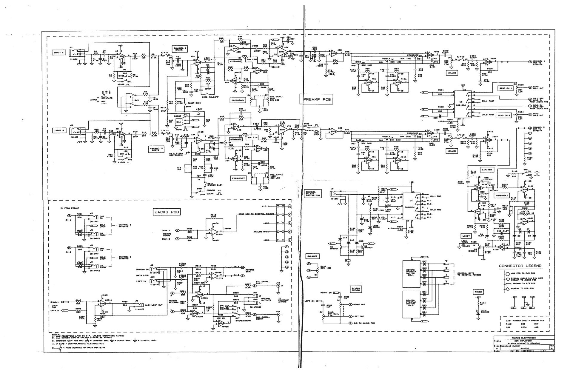
This is the schematic I've found:
http://www.travis-hartnett.com/Pearce_A ... n=download
I'm particularly interested in those parallel RC networks around the second opamp of Channel 2, as you can see in the schematic.
How does it work?
There is a switch (which is a little DIP switch on the front of the amp, I know) which is there to raise the gain (from the manual). What does it exactly do? It makes connection to ground, bypassing the 1M resistor, for that RC filter (4.7k resistor in parallel with 0.1 cap), isn't it?
Also, is that same RC filter (4.7k with 0.1 cap) always in the signal path or not? I mean, does that big 1M resistor make it essentially out from the circuit even when the DIP switch is out, or not?
Thank you very, very much in advance!!
Help with Channel 2 of Pearce G2R
-
ppluis0

- Diode Debunker
Hi,
The 1 Meg resistor is placed to mantain charged the electrolytic condenser (10 uF) to avoid to hear POP's when the user operates the associated switch.
When the switch remains open, the high value of that resistor in comparison with the others related to it, can be considered as an open network.
When the switch is closed, in order to increase the gain at that stage, also produces different frequency response due the combination of both rc networks in parallel, and both connects to gnd.
Cheers,
Jose
Thank you very much Jose!! Very useful..ppluis0 wrote:Hi,
The 1 Meg resistor is placed to mantain charged the electrolytic condenser (10 uF) to avoid to hear POP's when the user operates the associated switch.
When the switch remains open, the high value of that resistor in comparison with the others related to it, can be considered as an open network.
When the switch is closed, in order to increase the gain at that stage, also produces different frequency response due the combination of both rc networks in parallel, and both connects to gnd.
Cheers,
Jose
I'd like to ask you, when the DIP switch remains open (so that you say it can be considered an open network), does the RC filter made of 4.7k resistor and 0.1 cap make for some high mid-treble shift, or is it irrilevant compared to that parallel RC filter path, made of 10k resistor and 0.01 cap instead....?
Also, are those two RC filters both active when the Clean switch is selected, instead of the Crunch position..? (if you look at the ground connection of those RC filters, you can see that Clean/Crunch switch I'm talking about)
Thank you very much in advance, I think that you already answered to this but I guess that I don't exactly understand that "open network" expression, because of my poor knowledge of the language...!
Hope you can understand!
Thanks again!
-
ppluis0
- Diode Debunker
Hi J-fish,
I`m an argentine guy, so the spanish is my native language.
(Surely in my brain I have the idea to tell you one thing and at the same time my fingers wrote another thing in the keyboard... )
)
With the sw opened the only path that counts is formed by 1K, 10K and 0,01uF connected to ground. When you close that sw the other components change the gain and the freq response od that stage.
Cheers,
Jose
I`m an argentine guy, so the spanish is my native language.
(Surely in my brain I have the idea to tell you one thing and at the same time my fingers wrote another thing in the keyboard...
With the sw opened the only path that counts is formed by 1K, 10K and 0,01uF connected to ground. When you close that sw the other components change the gain and the freq response od that stage.
Cheers,
Jose