Trouble with optical switching

Tube or solid-state, this section goes to eleven!
Post Reply
User avatar
rackham
Information
Posts: 48
Joined: 08 Mar 2008, 23:27
Been thanked: 1 time

Post by rackham »

Hey guys

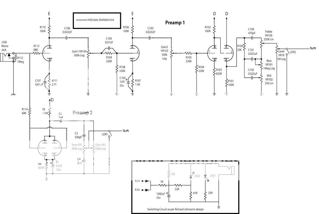
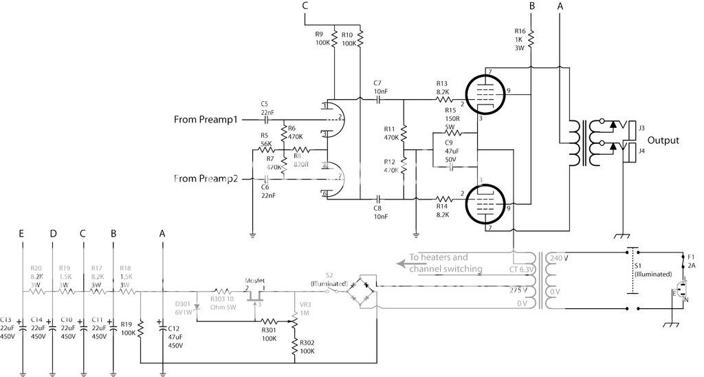
I've been building an amp, it's a 2 channel 'design' that I've cobbled together with an 18 watt power section. One preamp is basically and 18 watt Lite and the other is the Lead preamp from AX84.

Rather than having a bunch of different input jacks I adapted a design for optical switching using a couple of vactrols (VTL5C1) which send the signal from the preamps either to the PI or to ground.

The problem I'm currently having is that I'm getting bleed or cross-talk between the 2 channels which makes me think that the signal from the 2 channels isn't being properly grounded. I was wondering if a resistor between the vactrol and the caps that feed the PI (C5 and C6 on my schem below) would potentially help, but I also assume that this will alter the sound?

Image

Image

Image


Any suggestions gratefully received,

Cheers

Jon.

User avatar
JiM
Diode Debunker
Information
Posts: 967
Joined: 11 Mar 2008, 22:56
Completed builds: Completed builds :
Proco Rat
MXR MicroAmp in a volume pedal
TubeDriver (w/ NoS russian tube and big muff tone contol) + Phase 45 (w/ univibe cap ratio)
Dallas Rangemaster (w/ noisy OC75, negative ground)
SubCaster tube booster (w/ NoS russian tube, PtP)
Hot Harmonics
Music From Outer Space SubCommander in progress
Crackle Not OK
Simple bass blender in a 1590A
Bazz Fuss with a photo-darlington
Location: France
Has thanked: 70 times
Been thanked: 66 times
Contact:

Post by JiM »

I think your problem may be the ground itself : when you send a pre-amplified signal to ground, it may cause fluctuations of the ground potential, due to current in the (very small) resistance of the ground line.
Some ideas, to be confirmed by more skilled people :
- star grounding, at least around the vactrols
- decrease ground resistance (ie more conducting material, think of ground plane on a PCB)
- let the output of the unused channel floating, for example by connecting the vactrol in series with the signals, not to ground. This might not work with your clever PI design, though. :scratch:
I only give negative feedback.

User avatar
rackham
Information
Posts: 48
Joined: 08 Mar 2008, 23:27
Been thanked: 1 time

Post by rackham »

Thanks Jim

The layout that I've posted doesn't quite represent the way the amp looks now. :oops:

I've star grounded pretty much every ground connection separately in order to overcome some horrible noise issues that I had. The vactrols now have their own leads to a ground lug, but still there's this cross-talk problem.

I've compared my switching circuit today to that of the SLO and they're pretty similar. The SLO solution to 'bleed' seems to be to add another vactrol in series further up the signal chain so that might be a possibility...

User avatar
pz
Solder Soldier
Information
Posts: 217
Joined: 17 Aug 2007, 16:55
Location: Germany/Poland
Has thanked: 2 times
Been thanked: 50 times

Post by pz »

There are two factors to consider:
1. The LDR will never go down to 0Ohm,
2. two LDRs, one in series with the signal and second shunting the signal to ground form a voltage divider which attenuates the signal much more than a single LDR to ground, thus lowering the crosstalk.
I think the problem you have is generated mostly by unsufficient attenuation of the non active channel output.
I had a similar problem long time ago while i was building a 2 channel higain/clean tube amp with LDR switching.

With 4 vactrols you could do it that way:
LDRswitching.gif
LDRswitching.gif (4.45 KiB) Viewed 1178 times
With some slight changes in the control circuit you could use a SPDT relay instead of VTL2 & VTL4, saving some costs.

User avatar
rackham
Information
Posts: 48
Joined: 08 Mar 2008, 23:27
Been thanked: 1 time

Post by rackham »

Superb, thanks very much Piotr 8)

I bought a few vactrols anyway with the intent of sticking the ones that I didn't use in pedals.

My only concern now is where to put VTL1/VTL3 in my amp?

I think after the 1st preamp stage would be most convenient for board placement.

Thanks again for your help though mate.

Jon.

User avatar
pz
Solder Soldier
Information
Posts: 217
Joined: 17 Aug 2007, 16:55
Location: Germany/Poland
Has thanked: 2 times
Been thanked: 50 times

Post by pz »

I'd put the VTL1-4 just after the EQ sections and before the power amp.
If you want to be more sure there won't be oscillations and crosstalk between the channels, you could add another one LDR to mute the second stage of the drive channel. It's shown on the new schematic.
The value of the current limiting resistors fer LEDs depends on the U voltage and LEDs max current.
When the footswich is in open state the active channel will be the Preamp2.
You could also in a easy way add the frontpanel indicators showing the active channel. Just add two more R+LED sections, first parallel to (R3+LED1) and second parallel to (R10+LED3).
Attachments
LDRswitching2.gif
LDRswitching2.gif (11.66 KiB) Viewed 1145 times

User avatar
rackham
Information
Posts: 48
Joined: 08 Mar 2008, 23:27
Been thanked: 1 time

Post by rackham »

pz wrote:I'd put the VTL1-4 just after the EQ sections and before the power amp.
You'd be right too! :applause:

Works like a charm. I accidentally staked 2 extra turrets next to the existing vactrols when I was laying out the board, which made adding the extra ones a pretty easy job.

Good idea to add LEDs to the front panel too, I think I'll leave it as it is though as I've got a sheet of stainless steel for a faceplate and it's evil to drill. I've got an LED indicator in the footswitch anyway.

Thanks again for your help PZ, much appreciated.

Cheers

Jon.

Post Reply