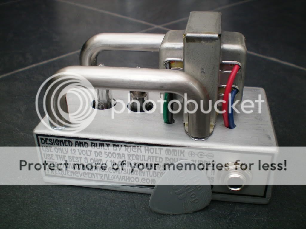
Finally got it finished this weekend, apart from a problem with the power supply, which I am asking for help on,
After I bolted the lot in the case the B+ dropped to ~6V rather than 60V
And I cannot for the life of me figure out why, I've had it back out the case and all over, Ive tried brand new IC's and also rebuilt a new one on breadboard with the same outcome.
Does anyone know what that could be, I still don't know how the power supply is working, I was just glad to find one that did.
Also to Rick, would you be willing to sell just a power supply made up and working???
Anyway, I have ran some leads from B+ out of the back of the case to a bench power supply providing 62V for now
I Redesigned the preamp stage with the 6111's
and paralleled 2 of the output stages
New Preamp:

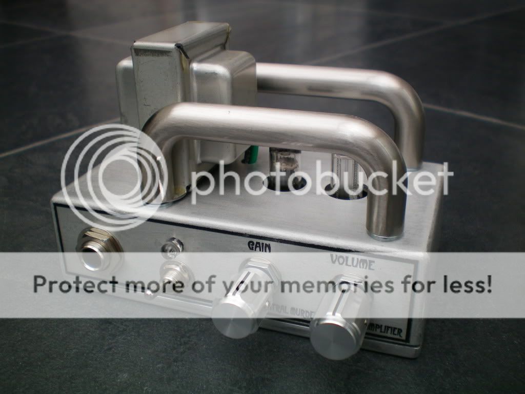
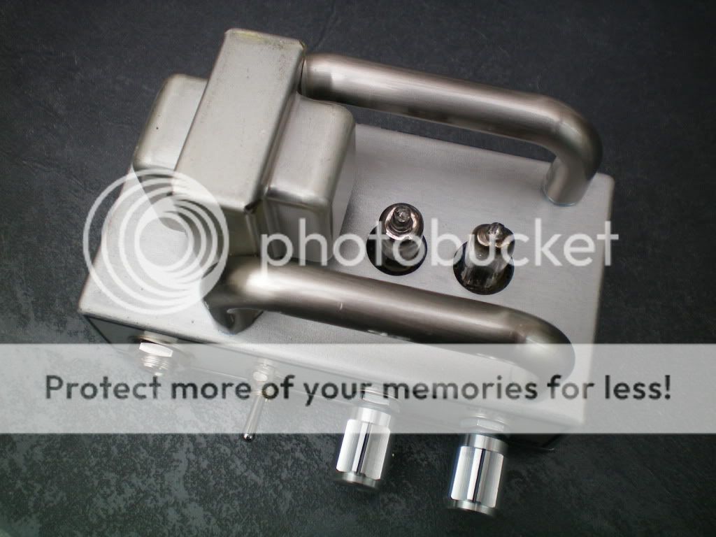
And here is my project.


I discovered I'm not to good at sticking letters on things
Oh well,
Here is a link to the vid of it,
Audio recorded with a Rode NT55