Hi Folks,
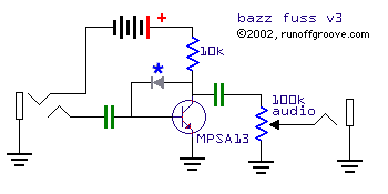
I was just wondering how you would go about calculating/working out/measuring the input impedance of a circuit like the Bazz Fuss
http://home-wrecker.com/bazz3.png
or any other circuit for for that matter?
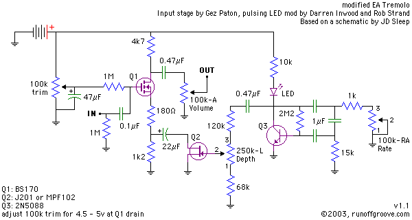
http://www.home-wrecker.com/EAtremolo.png
For instance is the 1M resistor on the input of the EA Tremolo involved or is that for something else (anti-pop?)
Furthermore, what is the ideal output impedance of a guitar pedal that is going to a guitar amp.
Thanks!
ff
Calculating/working out input Impedance
-
phatt

- Transistor Tuner
No it's not an inherently stupid question,, just inherently complicated to answer in simple terms as impedance is Not just simple DC resistance it is frequency dependent and that is a lot more complex.
Many factors come into it; The Impedance (Z Ohms) on the input will always be less than the Resistor across the input. Just because you hang a 1 meg resistor on the input does not automatically produce a 1meg Z Ohms input.
There is also the internal resistance of the active unit to be added to this value.
For those starting out be aware that there is a lot of not so clever circuits to be found no matter what the claim. Sure they may work but that does not mean they are mojo.
I would never dream of building a bass fuzz in the fashion you point to as it needs more than that to be a good reliable circuit.
Better minds here might have some pointers on how to develop good design techniques.
Your best bet is to learn the basics of transistor circuits and how they work.
Always remember everytime you look at a schematic there are 2 circuits happening not one.
So you set the DC conditions (set the DC bias or the quiescent point) for best possible reproduction and then fine tune the AC wiggle to taste.
In simple terms,,Amplification works by floating the AC wiggle on the DC potential,, the DC conditions have to be sorted before passing signal.
As to input Z and output Z the general rule is to make input as high as needed and output as low as you can design for best transfer of signal for minimum loss.
Hope it helps.
Phil.
Since you ask, the 1M is an anti-pop resistor indeed. For the first circuit, the input impedance can be derived with the aid of the small signal model of the transistor.
Phil is right, you need to take into account that the input impedance is dependent on frequency.
If you want a dirty approach, just to simplify things a bit, you can use the following one - for example, for the second circuit:
A 100n capacitor has a reactance of 16k at 100Hz. As we go up, the reactance falls - thus you can consider the cap to be a short circuit. The input impedance of a MOSFET is very high, so you can neglect it - it appears in parallel with the other 1M resistor, so the parallel combination leaves just the 1M. As I said before, even at 100Hz the cap's reactance is roughly 1.6% of the 1M resistor that appears is series with it (remember, the MOSFET is ruled out as a high impedance circuit that follows), so you can suggest that for all your frequencies of interest (82Hz is the lowest note of an electric guitar, perhaps muting the strings goes even lower, still not at the low end of the audio band) you can neglect the capacitor's reactance. Thus, you have two 1M resistors in parallel, so approximately a 500k input impedance.
All the above is just simplifying to get a quick answer that can sometimes be helpful. You must use a vectorial sum to derive the exact form of the frequency dependent impedance of course.
As for what output impedance is sufficient, I would say there is no exact number. Typical amps have an input impedance of 1M, so even some kiloohms of resistance are adequate. Remember, a single coil pickup has wiring resistance of about 10k (my SSL-5 has 12.9k) and easily drives an amp to wonderful tones.