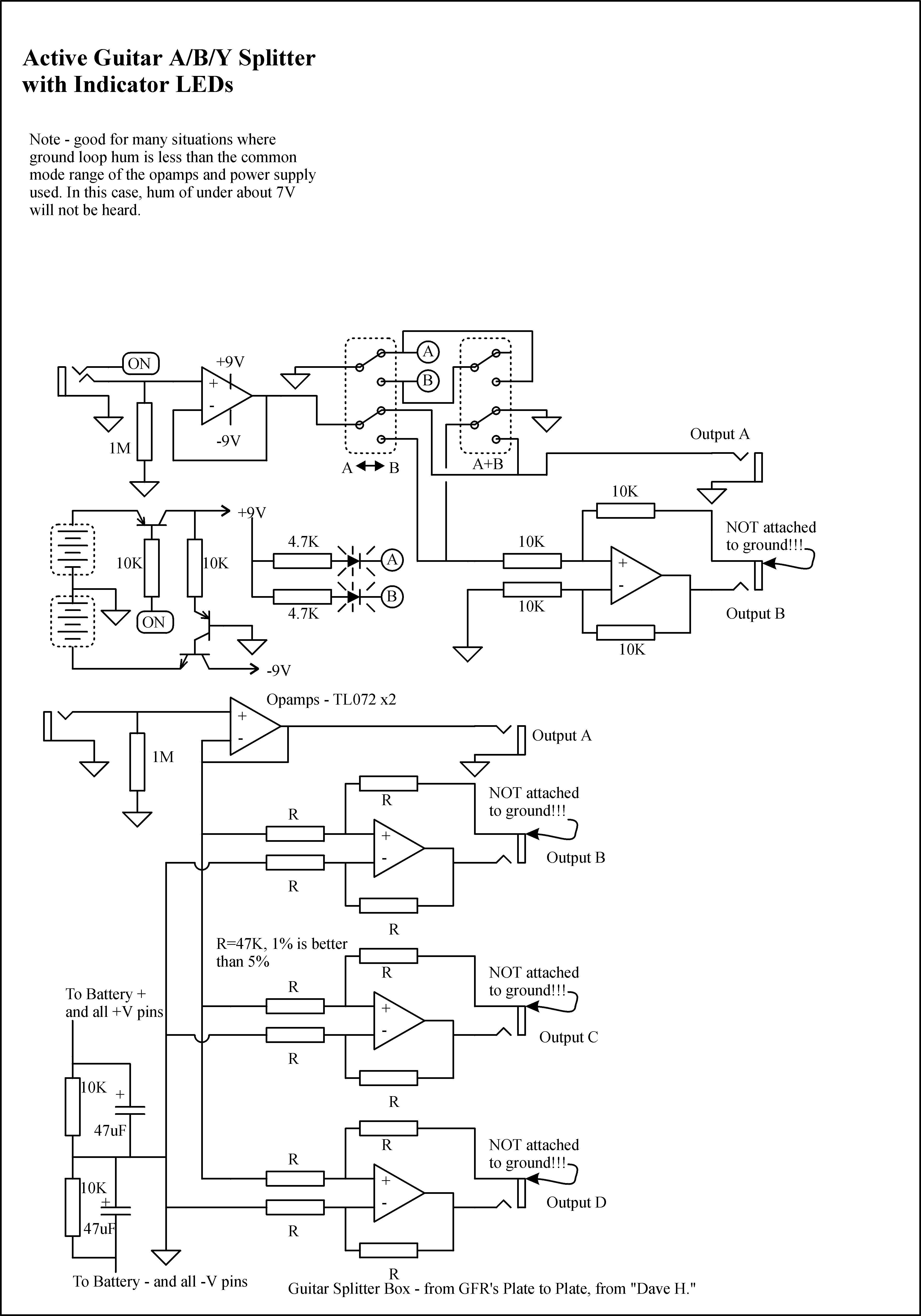
This is the schematic for the buffered A/B/Y pedal you can see in my build blog. I've built a couple of them for friends... does it's job good.
Since there's only two output, you really only need to have a polarity switch on one of them, but I guess having it on both allows for possibilities in any given situation. The biggest reason for the polarity reverse is to help match the sound when using two amps with different polarity outputs; like when you mix a tweed Bassman with a JTM45; or when you're using it to mix the two channels of a Twin Reverb together. It's a useful little tool. The bipolar supply ensures that it's nice and clean with even the loudest signals - it can take about 8 1/2 volts before it clips. If you wanted to increase the headroom even more, you could use a different supply for 12 or even 15 volts.
Suggestions:
1. don't use standard input jack power switching. Instead, us a PNP in series with the + end of the battery/DC input, and run a 10K from the base to the input jack stereo lug. Removes incoming ground noise from the input ground line.
2. Use that extra opamp that you're not using now to do the low voltage hum reducer from GEO. It will remove common mode ground hum.
Thanks! I will take your suggestions into consideration when I build my next one. I'd thought about using the extra amp for something like that, but it seems that it complicates the A/B switching, but... now that I think about it... yeah it wouldn't be hard to work out. Yeah, I'll give it a try.
"Analog electronics in music is dead. Analog effects pedal design is a dead art." - Fran
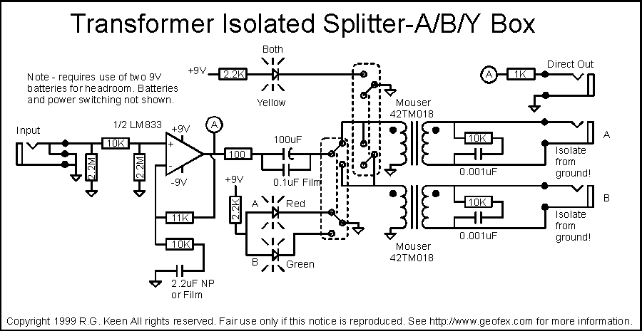
You might think about doing your ABY switching on the inputs instead of the outputs. The circuit for taking out common mode ground noise on one output is here http://geofex.com/FX_images/oaspltr.gif . The switching for ABY on the intputs is in there too; a slightly different version is here: http://geofex.com/FX_images/spltr2.gif .
I understand, but I worry about pops. The only place I was able to get the switching to be totally silent was on the outputs with the shorting arrangement. I can't remember if I tried the shorting on the inputs or not... I will try that. I may have just had the inputs flipping from one to the other, and that, of course, popped very badly. I have an idea for a 4 channel one I want to do, but that one will be switched with relays, so it will be easier to figure out.
Thanks for your help.
"Analog electronics in music is dead. Analog effects pedal design is a dead art." - Fran
Popping is only caused one of two ways:
(1) You couple a transient in, like from a relay coil
or
(2) You switch between two different DC levels. Even 25mV or so will make a very audible pop.
Ignoring 1 for the moment, I believe you have a DC offset problem with your first opamp. Using such a high input resistor and no feedback resistor makes opamps prone to give their worst DC offset behavior. I believe things would improve if you put a cap between the output of the first opamp and the feed to the second two opamps; also, put a 10K from both of the second opamps noninverting input and ground.
The cap prevents any DC offset from happening from the first opamp. The 10K resistors keep the + inputs of the two output opamps at DC ground, and are large enough that the first opamp can drive them easily. The inverting inputs are kept at ground by feedback from the outputs, and the 10K output resistor in concert with the 10K to ground on the noninverting inputs gives lowest DC offset performance.
That being said, shut muting is always quieter than series muting.
There's another variant of the true/inverting circuit you might like to mess with.
Imagine one of your two output circuits with 10K feedback/10K to inverting input. Also imagine two 10Ks in series between the output of the signal buffer and ground. The + input of the opamp connects to the junction of the two 10K's.
What's the output gain? It's zero. The four resistor connection is a single opamp differential amplifier with its inputs shorted together. If you short the upper 10K, you get a gain of +1. If you short the lower 10K, you get a gain of -1.
So you can get +1, -1, and zero from the same circuit by adding two more resistors. You might be able to get your muting this way as well. Just a thought.
Also: since there are only two cases, either the two amps are in phase or they are not, you only need ONE of the two outputs to be able to flip phase.
That makes it easier, because you can then use a series resistor from the first opamp buffer to the two output opamps, and shunt-mute them to ground to select ABY. The phase flipper goes on the output and gives you inverted phase on one of them to get polarity right.
My circuits are not tone-suckers; they are tone-creators!
Stay tuned for mkII version with the improvements RG has suggested, though the mkI shown here works okay if you're impatient. Built a couple for buddies and they're happy.
"Analog electronics in music is dead. Analog effects pedal design is a dead art." - Fran

