Blendable Klon-type Overdrive

Stompboxes circuits published in magazines, books or on DIY electronics websites.
Post Reply
User avatar
markm
Diode Debunker
Information
Posts: 787
Joined: 26 Jun 2007, 14:41
Location: U.S.A.
Been thanked: 10 times

Post by markm »

Hi Everyone!
trying to put some of my theory to work here and came up with this.
I've been thinking, and that is dangerous sometimes for all of us,
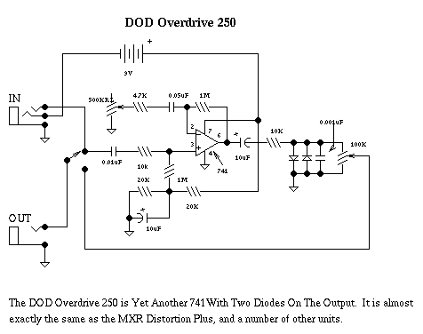
But, I came up with this Blendable type OD based on the OD250 type circuit that for the most part, incorporates the standard OD250 circuit along with a "Clean" version with no clipping diodes and a TL071 op amp.
The idea is to have the Gain control set-up similar to the Klon or The Crank using a Dual Gang pot where when one side is max, the other is minimum and so on.
I'm a bit confused as to whether this here would work as I have the 2 circuits sharing the same input cap and also they share the same output to the volume control.
Any opinions as to whether they would work together when set up like this or, should I just call it a day on this one?!
Please have a look at the layout.
I have no schem as it's just 2 OD250's put together.


Image

User avatar
tuemmueh
Solder Soldier
Information
Posts: 165
Joined: 26 Jun 2007, 23:30
Has thanked: 7 times
Been thanked: 2 times

Post by tuemmueh »

Would you like to post the schematic of your layout? I think it's much easier to follow a schematic than a layout.

User avatar
markm
Diode Debunker
Information
Posts: 787
Joined: 26 Jun 2007, 14:41
Location: U.S.A.
Been thanked: 10 times

Post by markm »

tuemmueh wrote:Would you like to post the schematic of your layout? I think it's much easier to follow a schematic than a layout.

From my original post;
Please have a look at the layout.
I have no schem as it's just 2 OD250's put together.


Here's a schem of the OD250......think of it X2.
http://www.montagar.com/~patj/dodoverd.gif

Perhaps this may sound odd to you but, when I did this I didn't sit down and draw a schem of it as I had in my head the idea of what I wanted to do, I just added an additional OD250 circuit to an existing layout that I had, set the 2 gains up to operate on a Dual Gang pot and added the buffer per advice of "slacker" from the other site. One side has clipping diodes one side doesn't.
Check the OD250 schem above and , there you have it.
I apologize, I very rarely draw schems for anything I do because I'm not that professional.....I'm a circuit hack! Maybe when this thing is finished, AG could draw up a schemo as he's VERY good at it.

User avatar
bajaman
Old Solderhand
Information
Posts: 4549
Joined: 26 Jun 2007, 21:18
Location: New Brighton, Christchurch, NZ
Has thanked: 596 times
Been thanked: 2061 times

Post by bajaman »

That looks good markm - and emphasises what we are here - a co-operative sharing community :wink:
Thanks for sharing - you can post your Buckaroo here too ( start a new topic thread )if you feel inclined :wink:
Your work is appreciated by many friends here :D
Cheers
Steve

User avatar
markm
Diode Debunker
Information
Posts: 787
Joined: 26 Jun 2007, 14:41
Location: U.S.A.
Been thanked: 10 times

Post by markm »

Thank you very much Steve!
BTW, is that a drink in your hand?? :D

User avatar
theblackman
Resistor Ronker
Information
Posts: 250
Joined: 27 Jun 2007, 00:43
Location: Western Australia
Has thanked: 10 times
Been thanked: 3 times

Post by theblackman »

looks like a 2002 plantagenet cab sav, a man of fine taste i see! :D :D

User avatar
bajaman
Old Solderhand
Information
Posts: 4549
Joined: 26 Jun 2007, 21:18
Location: New Brighton, Christchurch, NZ
Has thanked: 596 times
Been thanked: 2061 times

Post by bajaman »

Yes - red wine on New Year's Day 1998!!!!

User avatar
Goop_buster
Solder Soldier
Information
Posts: 247
Joined: 22 Jul 2007, 22:31
Been thanked: 7 times

Post by Goop_buster »

Very interesting idea thanks :D

I think I have to make a schematic for myself anyway :wink: .


I think I see some problem here. Not the the input but the circuits are kind of parellelled but one of them got (output level-limiting) diodes at the end.
So how do they blend?

User avatar
markm
Diode Debunker
Information
Posts: 787
Joined: 26 Jun 2007, 14:41
Location: U.S.A.
Been thanked: 10 times

Post by markm »

Goop_buster wrote:Very interesting idea thanks :D

I think I have to make a schematic for myself anyway :wink: .


I think I see some problem here. Not the the input but the circuits are kind of parellelled but one of them got (output level-limiting) diodes at the end.
So how do they blend?
It worked Okay but had some issues. :cry:

User avatar
briggs
Tube Twister
Information
Posts: 1971
Joined: 12 Jul 2007, 10:02
my favorite amplifier: Briggs Custom Suprono
Completed builds: Too many to still class myself as sane....
Location: Breaking into Heaven.
Has thanked: 27 times
Been thanked: 128 times
Contact:

Post by briggs »

Whatever happened to this mark? Did you ever try breadboarding up that scheme I sketched up? It sounded OK... Just needed some tweaks!
Image

I am Klon.

User avatar
trevize
Breadboard Brother
Information
Posts: 64
Joined: 16 Aug 2007, 16:28
Location: Near Venice, Italy

Post by trevize »

what kind of issues? Have you thought about putting an inverting input buffer and blend the two signal with an inverting mixer?
I think that the mixing section would probably be the most important.

User avatar
briggs
Tube Twister
Information
Posts: 1971
Joined: 12 Jul 2007, 10:02
my favorite amplifier: Briggs Custom Suprono
Completed builds: Too many to still class myself as sane....
Location: Breaking into Heaven.
Has thanked: 27 times
Been thanked: 128 times
Contact:

Post by briggs »

This is the schem I was fiddling with tre: https://img404.imageshack.us/my.php?ima ... ikevs2.jpg

If you bash it up on a breadboard it sounds pretty cool.

The "issues" where to do with getting an even transition between OD and clean boost...
Image

I am Klon.

User avatar
trevize
Breadboard Brother
Information
Posts: 64
Joined: 16 Aug 2007, 16:28
Location: Near Venice, Italy

Post by trevize »

I'm after something simpler. I think it would be possible to have a similar result wih just a dual opamp and without dual ganged pots.
I'm going to breadboard and experiment this circuit today.

Image

User avatar
bajaman
Old Solderhand
Information
Posts: 4549
Joined: 26 Jun 2007, 21:18
Location: New Brighton, Christchurch, NZ
Has thanked: 596 times
Been thanked: 2061 times

Post by bajaman »

Sorry Trevize
Your circuit will not work as you intend, because the clipping diodes are always connected to the input of the second op amp - your balance control will clean up slightly in the centre, but distort equally at both ends of its's travel.
Cheers
bajaman

User avatar
briggs
Tube Twister
Information
Posts: 1971
Joined: 12 Jul 2007, 10:02
my favorite amplifier: Briggs Custom Suprono
Completed builds: Too many to still class myself as sane....
Location: Breaking into Heaven.
Has thanked: 27 times
Been thanked: 128 times
Contact:

Post by briggs »

Yeah, your gonna need some buffers or mix resistors on there.
Image

I am Klon.

User avatar
trevize
Breadboard Brother
Information
Posts: 64
Joined: 16 Aug 2007, 16:28
Location: Near Venice, Italy

Post by trevize »

ok I will try with two fet buffer and see what happens. thank you!

User avatar
markm
Diode Debunker
Information
Posts: 787
Joined: 26 Jun 2007, 14:41
Location: U.S.A.
Been thanked: 10 times

Post by markm »

trevize wrote:what kind of issues? Have you thought about putting an inverting input buffer and blend the two signal with an inverting mixer?
I think that the mixing section would probably be the most important.
The issues were basically Volume was way too low on the clean side and the OD was very "harsh" sounding.
I put it on the back burner to make room for several other projects.
As always, I have too much going on right now! :lol:
Join together with the "Banned"!

Post Reply