more effectively without the scirrocco of noise they produce when like, 6 or 8 of them are engaged.
so me and petey were looking around at easy gates, and found one on techniguitare.. but petey said someone here said it didn't work.
well, if they built the vero in the pdf on that site, it sure won't... they have all kinds of mistakes in it. CLOSE, but no cigar as groucho used to say.
so i took a look and saw the problem... they had reversed a couple component values from the schematic, and had pin 5 of the opamp grounded...when it should have had a 100n cap and 2.2m resistor there. i think that jumper to ground is why it wouldn't work as shown.
for reference, here's the forum page with files for the project:
http://techniguitare.com/forum/fiches-t ... t9557.html
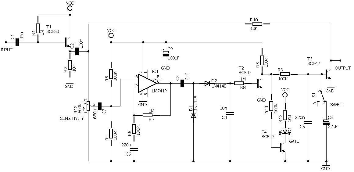
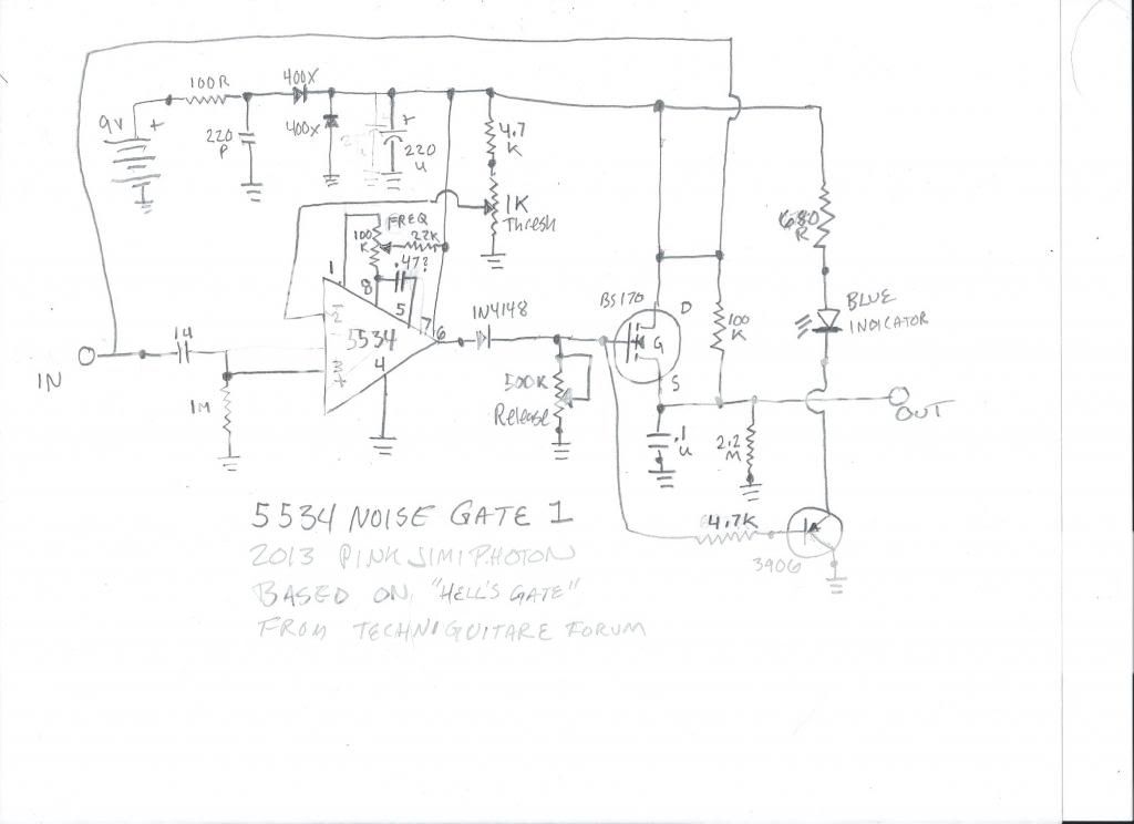
here's the original schematic:

i looked at it, and it looked easy, and doable on vero cuz it was simple.
so i aimed to overcomplicate it some.
also, they specced tl071, and i don't have any... i have 741's, but... i also have ne5534's, which are low noise jfet single opamps. an ass load of 'em.
so i figured i'd adapt it.
now, i've used a similar kind of 741with frequency compensation... and it sounded good, but without the frequency comp circuitry it's noisy as f***.
so i looked at the data sheet, looked fairly simple... a cap between pin 8 and 5 (don't know what value is good, i wrote .47 on the schem but on the vero it shows sockets to experiment with)
and a pot between pins 1 and 8, with a 22k resistor being fed by the b+ voltage.
i THINK it should enable finding the frequency for where it cuts off... not sure. need advice on this part, cap values and such please if possible.
if it's not worth f'n with, please illuminate me so i can ditch the stuff... or if i made some other dumb mistakes..
likely, with me. :icon_eek:
here's the data sheet or the 5534:
http://www.onsemi.com/pub_link/Collateral/NE5534-D.PDF
also added an ass load of power supply filtering/protection... current limiting resistor, snubber, diode in line and diode reverse biased to ground and a big honkin' 220u cap, hoping that by doing so it will make this thing as quiet as possible in operation.
added in a simple circuit to flash an led white the gate is operating. didn't bother with t/b switching stuff.
here's the schematic first:
and here's the vero i worked up... a second set of eyes is always welcome in these matters of course... if someone can give me a thumbs up or down, i plan on building this puppy posthaste.
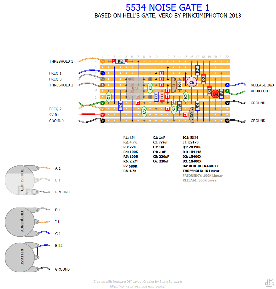
so... i would really appreciate advice, criticisms, GFY's, attaboys, whatever ya go!
thanks brothers...peace