Page 2 of 3
Re: ValveCaster Mods
Posted: 04 Mar 2018, 19:20
by snk
Ok. I understand from the posts above that one part of the tube could receive the regulated, 12V max, current (because it can't get more than 12.6V), while another part of the tube can handle stronger power, and thus could get unregulated power : am i correct ?
That's very interesting, i never realized that

I may consider this as a worthy mod. But, as such a design is new to me, i am not fully understanding yet what you wrote and the schematics (if they feature errors or wrong values, i can not notice it)

Re: ValveCaster Mods
Posted: 04 Mar 2018, 21:13
by Manfred
ppluis0 wrote:Hi Manfred,
Perhaps was a mistake of Mr Holt at the time to draw his schematic.

I think that a constant current source should look like this:
[
Image ]
The current is calculated as: (Vled-Vce)/Re and the Hfe of the transistor is irrelevant.
Cheers,
Jose
Hi Jose,
thanks for your reply, I fully agree with you.
Re: ValveCaster Mods
Posted: 04 Mar 2018, 23:22
by marcao_cfh
A 12A_7 have two heaters (the part that lights up). The heaters have a "set" voltage to work. The 12 means 12V (12,6V actually), so you can wire the heaters in series and power them with 12,6V. You'll need to supply 150mA. But you can also wire the heaters in parallel, powering them with 6,3V but with 300mA.
But this is just for the heaters, which, well, heats the tube, so it have the optimal temperature to work. The rest of the tubes works with way higher voltage, something like 200V or even more (but less tha 400V or 450V, I don't remember the maximom voltage a 12A_7 can handle).
You can think this way: the tube it's something like a transistor, that can work with high voltage. But it have a "special on/off switch", that is the heater, which works with a specific voltage.
Re: ValveCaster Mods
Posted: 05 Mar 2018, 00:11
by deltafred
The easiest way to get the voltage down to 12.6v is to put a resistor in series with it so the heater is 12.6v otherwise you will shorten the life of the heater (and the valve).
Measure your heater voltage now, then subtract 12.6 from it and that is what you need to drop across the resistor.
Using ohms law R = volts/amps, = (the figure from above) / 0.15 ohms. (If you need to drop 4 volts then R = 4 / 0.15 = 27 ohms.)
I would use a 2w resistor so it can dissipate the power without getting too hot.
Re: ValveCaster Mods
Posted: 07 Mar 2018, 22:54
by snk
marcao_cfh wrote:About the tone pot, try this:
- disconnect the tone pot and C4;
- connect C3 to lug 3 of the volume pot;
- connect one pin of C4 to lug 3 of the volume pot, and the other pin to lug 3 of the tone pot;
- connect lug 2 of the tone pot to ground.
The schematic you've used have signal>tone pot>filter cap>ground path for the tone pot, while others have signal>filter cap>tone pot>ground path. Doing these things changes the path from the first option to the 2nd. Try and see if this fixes this issue.
Also, if you think it's working in reverse, just move the wire from lug 3 to lug 1.
Hi Marcao
I just tried it tonight : it works perfectly as expected now, thank you very much.
The Valvecaster is getting really interesting now

I also tried the bass boost circuit, but i didn't hear any difference.
I will install a regulator next week.
I might also try the diode clipping mod

Re: ValveCaster Mods
Posted: 08 Mar 2018, 20:34
by snk
I'm planning to add the 12V regulator for the heater from a veroboard : as it is the first time i'm designing a veroboard, could anyone tell me if the schematic is correct, please ?

Also, someone wrote that the first capacitor value (2200µF) was "overkill", but i just borrowed the values from a schematici found on the web : which value would be better for this circuit ?
Re: ValveCaster Mods
Posted: 11 Mar 2018, 21:19
by snk
Little bump : is this veroboard schmeatic correct ?


Or should i try
this:
Re: ValveCaster Mods
Posted: 12 Mar 2018, 15:24
by marcao_cfh
This one should work:

I would use 100uF 50V for C1 and something between 10uF and 100uF 25V for C2.
Re: ValveCaster Mods
Posted: 12 Mar 2018, 19:07
by snk
Thank you !
I'm dully noting your suggested values for the capacitors.
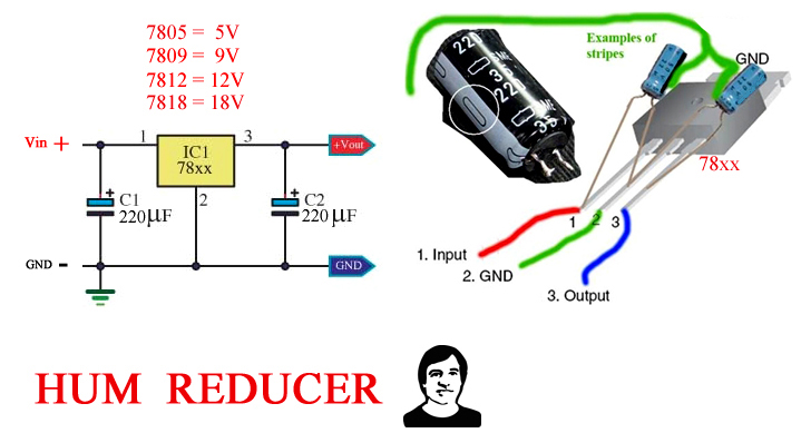
What about the "hum reducer" circuit (avoiding a veroboard) ? Would it end to be the same ?
Re: ValveCaster Mods
Posted: 13 Mar 2018, 20:21
by snk
Hello
Two last questions :
1- What will the values of C1 and C2 change (why chosing 100µF instead of 220µF or another value) ?
2- I have read that starved plates designs expect a very high input impedance load : should i include a buffer inside the enclosure, before the circuit ?
Re: ValveCaster Mods
Posted: 15 Mar 2018, 20:10
by marcao_cfh
The values sets how much filtering you'll have. In most cases, they're not too much critical. That "hum reducer" is basically the same circuit but without a board; you can do this way, but there'll be lots of parts' leads exposed, so it's easy to get some circuit shorts.
Re: ValveCaster Mods
Posted: 15 Mar 2018, 21:32
by snk
Thank you, Marcao.
From what i see, there is no cut on the veroboard you posted, right ?
grrr ! I only have 35V 100µF caps

Re: ValveCaster Mods
Posted: 15 Mar 2018, 23:51
by marcao_cfh
Yes, no cuts. And you can use 35V caps, just don't power it with more than 35V. If you're still using 15V, there's no problem.
Re: ValveCaster Mods
Posted: 16 Mar 2018, 08:39
by snk
Thank you for confirming.
That's too bad : i have dozens of 100µF caps, but most of them are 16V rated

- For C1, i have a 220µF 35V Nichicon cap, and a 100µF 35V Nichicon cap : so, you're saying that the 100µF will work best ?
- For C2 i have a 47µF 25V Nichicon cap : i guess it's perfectly bewteen the 10 and 100 values you suggested.
I can also wait a bit more, and buy the best values.
Could you tell if the filtering will be worse if i
increase or
decrease the capacitor values ?
Re: ValveCaster Mods
Posted: 16 Mar 2018, 13:39
by marcao_cfh
If you decrease: less filtering and more power supply noise.
If you increase: more filtering and less power supply noise. But there's a point you won't notice any difference if you increase the cap value.
I'd try with the values you have in hand. Any value for C1 and 47uF for C2, or 220uF for C1 and 100uF for C2.
Re: ValveCaster Mods
Posted: 16 Mar 2018, 16:00
by snk
Perfect, that makes sense, i'm learning

Re: ValveCaster Mods
Posted: 18 Mar 2018, 08:43
by snk
I made the regulator board, soldered it to the circuit, and tried :
- first, it didn't work (but it was because while installing it, one resistance on the valve socket got unsoldered on one side).
- I fixed that, and it worked
- Then, i closed the enclosure, screwed the knobs caps, and tried again : it didn't work
I checked the socket to see if another resistor or capacitor got unsoldered in the meantime, but everything seems well in place...
Then, i unsoldered the regulator board, and tried with the previous settings (no regulator board) : it worked again.
Is the 7812 very sensitive ? I have plugged it to a 15V power supply, so everything shuold be fine... I plugged it first with the wrong polarity, but only for a couple seconds...
The wires seems ok, i don't know what is going wrong

Re: ValveCaster Mods
Posted: 19 Mar 2018, 21:43
by snk
Mmmh, little bump, as this thing must be obvious (There are so few components), but i can't figure out what's going wrong here...
Without the board, it works, with the board, it worked several seconds, and a few minutes later it doesn't work any more
Re: ValveCaster Mods
Posted: 19 Mar 2018, 22:06
by 95H
Hi,
typical circuit for the 78xx should be like the pic below.
The capacitors close to the 78xx are only for blocking of HF oscillating, the values described like above look not correct. Keep in mind, if voltage Uxx on output get's higher than the input voltage UE, the 78xx will die immediately. So use the diode for protection.
C1 & C3 multilayer ceramic
Hope you have protection against my bad English.


- u3p_01 (1).gif (3.75 KiB) Viewed 3087 times
Re: ValveCaster Mods
Posted: 19 Mar 2018, 22:43
by snk
Hi, 95H, thank you for your answer.
I didn't use a diode, and used only 2 capacitors (electrolytics).
So, it might be a dead 7812... I will order a couple more, to try with a diode and different cap values (as well as a third capacitor).
In the meantime, I will try to "translate" the circuit schematic into a veroboard.
Don't worry, your english is fine