hey there I wasnt sure what this was but I like having the BIAS knob for that weird effect. i now realise this is a fuzz face? but with a bias control?
I did a bit of a botch job as I am totally noob I just soldered all the components together. I only had 10k pots for both knobs.
I replaced the two transistors with 2N2222's.
I used a 20k input resistor on the 9v that should go into a 33k it then goes straight into the collector of one and base of the other resistor.
Anyway it sounds ok but there is TONNES of interference and noise check it out I uploaded to youtube and also took some photos and included the original schematic I am following:
Original post second from bottom=
https://www.freestompboxes.org/viewtopic ... ret#p86463
problems with MESSY FUZZ
i replaced the 10k coming from the capacitor to a 10k pot I read it would act as a gain control? he said to put a capacitor across the back of it or something . I dunno what that means.
Here is ther post about replacing the resistor with a pot:
http://www.tdpri.com/threads/anyone-wit ... am.237244/
"Just change the 1k resistor to a pot with the electrolytic on the wiper, and the bias pot to an 8.2k resistor, or leave as is. https://www.freestompboxes.org/viewtopic ... ret#p86463"
what does he mean about a electrolyte on the wiper?? I added a pot 10k but it isnt so much a gain pot lol. All the pots I have interact in very interesting ways I like it. But unfortunately this noise issue is making my pedal useless.
I tried replacing the 2n2222's with MPSA13's and it was not so nice. REALLY compressed on high gain... When the pot if turns up I put in for gain, just seems to all compress. Didnt have that with the 2n2222 .. I want more distortion on the 2n2222 how do I do that? give it more current?
I put it into a stripboard and it's all a bit cleaner but the terrible noise is still there.
Any ideas ?
Wish it was a clean signal as I actually really like it.
Did I ground everything ok? The battery - plus all the earth connections all connect with the cable/output negative? I am probably doing something obvious ...
Here is a video of how it is now...
Any ideas ?
Wish it was a clean signal as I actually really like it.
Did I ground everything ok? The battery - plus all the earth connections all connect with the cable/output negative? I am probably doing something obvious ...
Here is a video of how it is now...
-
Nocentelli

- Tube Twister
Information
- Posts: 2222
- Joined: 09 Apr 2009, 07:06
- Location: Leeds, UK
- Has thanked: 1155 times
- Been thanked: 954 times
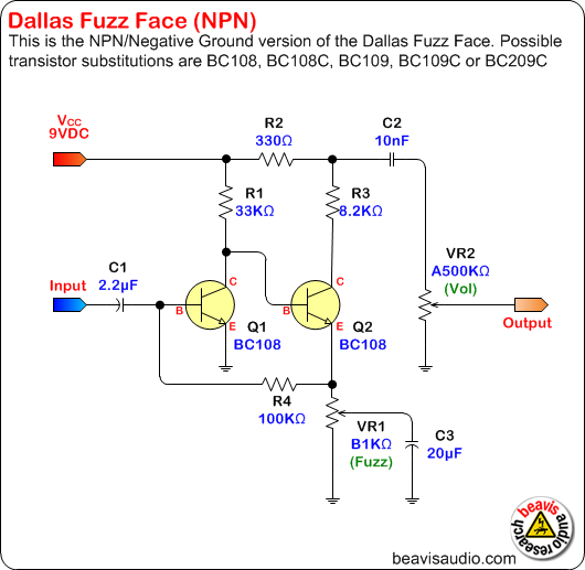
In a "standard" fuzzface, the output capacitor that leads to the volume pot would NOT be connected directly off the Q2 collector, but instead taken from the node between the 330 ohm resistor and the bias pot. Some people complain that this makes the fuzzface output a little low, and a common mod is to increase it slightly to 470ohm.
However, I suspect your noise problem is caused by taking the output direct from the collector: Your output level is probably extremely high, and I suspect this means you have the volume/output pot rolled down very low which could make the amount of hiss and noise very high.
Also, the resistor between Q2 emitter and Q1 base would usually be 100k NOT 10k: It is as high as 120k/150k and as low as 47k in some fuzzface-variant circuits, but never as low as 10k.
The "gain pot" suggested by replacing the 1k resistor off Q2's emitter is just the standard fuzzface "fuzz" control: It will allow you to reduce your gain but not increase it (since your circuit effectively has this control preset at maximum)
However if you want a pot that will add more filth, you could try adding a 250k pot in series with the non-standard 10k feedback resistor.
[Late edit - Looking at the pictures of the original (non-vero) layout, the "22k" Q1 collector resistor looks a bit more like red-red-black-black-red which would suggest 220 ohm, not 22k and would definitely mess stuff up.]
However, I suspect your noise problem is caused by taking the output direct from the collector: Your output level is probably extremely high, and I suspect this means you have the volume/output pot rolled down very low which could make the amount of hiss and noise very high.
Also, the resistor between Q2 emitter and Q1 base would usually be 100k NOT 10k: It is as high as 120k/150k and as low as 47k in some fuzzface-variant circuits, but never as low as 10k.
The "gain pot" suggested by replacing the 1k resistor off Q2's emitter is just the standard fuzzface "fuzz" control: It will allow you to reduce your gain but not increase it (since your circuit effectively has this control preset at maximum)
- fuzzface gain pot.gif (5.06 KiB) Viewed 2598 times
[Late edit - Looking at the pictures of the original (non-vero) layout, the "22k" Q1 collector resistor looks a bit more like red-red-black-black-red which would suggest 220 ohm, not 22k and would definitely mess stuff up.]
modman wrote: ↑ Let's hope it's not a hit, because soldering up the same pedal everyday, is a sad life. It's that same ole devilish double bind again...
In a "standard" fuzzface, the output capacitor that leads to the volume pot would NOT be connected directly off the Q2 collector, but instead taken from the node between the 330 ohm resistor and the bias pot. Some people complain that this makes the fuzzface output a little low, and a common mod is to increase it slightly to 470ohm.
ME:
COOL! this works better but now my BIAS pot makes the volume go down when I turn it down..
YOU:
However, I suspect your noise problem is caused by taking the output direct from the collector: Your output level is probably extremely high, and I suspect this means you have the volume/output pot rolled down very low which could make the amount of hiss and noise very high.
ME:
NOPE I had the volume pot up max it sounded best like that. Maybe more noise.. I had only 10K pots but I removed it as it seemed to do nothing after I put the output from the BIAS instead. I guess I should have replaced it with something else? But it just goes to ground and output and I have no output from this now as it is coming form the BIAS pot.
With all the changes I have made and heard it has always has this same noise issue! I still have the noise issue after all the changes you suggested...
It is like its picking up loads of interference or something. At one point I heard a radio station over my amplifier...
YOU:
Also, the resistor between Q2 emitter and Q1 base would usually be 100k NOT 10k: It is as high as 120k/150k and as low as 47k in some fuzzface-variant circuits, but never as low as 10k.
ME:
So I replaced with a POT in series with the 100K the pot is 500K for filth.
YOU:
The "gain pot" suggested by replacing the 1k resistor off Q2's emitter is just the standard fuzzface "fuzz" control: It will allow you to reduce your gain but not increase it (since your circuit effectively has this control preset at maximum)
ME:
THANKS!! I dont want to reduce my gain really as it is nice how it is so I used this pot for the filth pots you suggested which I talk about below...
YOU:
However if you want a pot that will add more filth, you could try adding a 250k pot in series with the non-standard 10k feedback resistor.
ME:
I am not totally sure what you mean here. I only have a 500K POT available which I have used in series with the 100K resistor you suggested I use. I gues I should use a lower value as I have such a high value resistor in series? It does seem to work in its current form... It doesnt do much. The BIAS does a lot but as I said it doesnt stay at the same volume now, when I turn down the BIAS>VOLUME DOWN.
YOU:
Late edit - Looking at the pictures of the original (non-vero) layout, the "22k" Q1 collector resistor looks a bit more like red-red-black-black-red which would suggest 220 ohm, not 22k and would definitely mess stuff up..
ME:
No it is 22K must have looked strange in pic. it is brown brown black black brown...
I am not sure what I am doing lol but I have a great array of sounds coming out of this. I dont care if its always on maximum volume. I found a 50K and 500K pots in another old pedal I have taken and I can use. So I used them. I guess this will throw everything off again, in the schematic it says to use a 25K pots for BIAS and a 100K pot for volume which I do not even have attacked anymore so I am using the 500K for filth...
As long as I have two dials that sculpt and interact with eachother and the sound, if its always on maximum gain and volume I dont care. I love the BIAS squishy control and what the filth is doing if it would stay the same volume when I turn bias down.
I am probably missing something to replace what the volume pot used to be doing, just to keep it all connected, as I moved the output the volume would just be connected to the ground and collector... I will try putting a 100K resistor in place of what the pot used to do?
I DREW IT OUT, WHAT I HAVE NOW!!!
This is really fun and I REALLY appreciate the help you have given me so far!!!!
Just gotta get a clean signal outa this bad boy then once I know the basic layout I am sticking with I can tweak things to get what I want out of it.
ME:
COOL! this works better but now my BIAS pot makes the volume go down when I turn it down..
YOU:
However, I suspect your noise problem is caused by taking the output direct from the collector: Your output level is probably extremely high, and I suspect this means you have the volume/output pot rolled down very low which could make the amount of hiss and noise very high.
ME:
NOPE I had the volume pot up max it sounded best like that. Maybe more noise.. I had only 10K pots but I removed it as it seemed to do nothing after I put the output from the BIAS instead. I guess I should have replaced it with something else? But it just goes to ground and output and I have no output from this now as it is coming form the BIAS pot.
With all the changes I have made and heard it has always has this same noise issue! I still have the noise issue after all the changes you suggested...
It is like its picking up loads of interference or something. At one point I heard a radio station over my amplifier...
YOU:
Also, the resistor between Q2 emitter and Q1 base would usually be 100k NOT 10k: It is as high as 120k/150k and as low as 47k in some fuzzface-variant circuits, but never as low as 10k.
ME:
So I replaced with a POT in series with the 100K the pot is 500K for filth.
YOU:
The "gain pot" suggested by replacing the 1k resistor off Q2's emitter is just the standard fuzzface "fuzz" control: It will allow you to reduce your gain but not increase it (since your circuit effectively has this control preset at maximum)
ME:
THANKS!! I dont want to reduce my gain really as it is nice how it is so I used this pot for the filth pots you suggested which I talk about below...
YOU:
However if you want a pot that will add more filth, you could try adding a 250k pot in series with the non-standard 10k feedback resistor.
ME:
I am not totally sure what you mean here. I only have a 500K POT available which I have used in series with the 100K resistor you suggested I use. I gues I should use a lower value as I have such a high value resistor in series? It does seem to work in its current form... It doesnt do much. The BIAS does a lot but as I said it doesnt stay at the same volume now, when I turn down the BIAS>VOLUME DOWN.
YOU:
Late edit - Looking at the pictures of the original (non-vero) layout, the "22k" Q1 collector resistor looks a bit more like red-red-black-black-red which would suggest 220 ohm, not 22k and would definitely mess stuff up..
ME:
No it is 22K must have looked strange in pic. it is brown brown black black brown...
I am not sure what I am doing lol but I have a great array of sounds coming out of this. I dont care if its always on maximum volume. I found a 50K and 500K pots in another old pedal I have taken and I can use. So I used them. I guess this will throw everything off again, in the schematic it says to use a 25K pots for BIAS and a 100K pot for volume which I do not even have attacked anymore so I am using the 500K for filth...
As long as I have two dials that sculpt and interact with eachother and the sound, if its always on maximum gain and volume I dont care. I love the BIAS squishy control and what the filth is doing if it would stay the same volume when I turn bias down.
I am probably missing something to replace what the volume pot used to be doing, just to keep it all connected, as I moved the output the volume would just be connected to the ground and collector... I will try putting a 100K resistor in place of what the pot used to do?
I DREW IT OUT, WHAT I HAVE NOW!!!
This is really fun and I REALLY appreciate the help you have given me so far!!!!
Just gotta get a clean signal outa this bad boy then once I know the basic layout I am sticking with I can tweak things to get what I want out of it.
- Attachments
-
-
-
-
-
Maybe I should start from scratch with a better schematic now I kinda know what I am doing better... Also I can order the right pots and other parts.
I liked this one as I want the BIAS pot more than volume or gain. I like the FILTH pot. If I could get it all working better together. At some stages the two pots were really interacting in an interesting way creating loads of different tones. Now I kinda lost that as BIAS just makes everything go quiet unless its nearly up all the way.
Anyway I am sure what I have needs a few little tweaks and will function much better but if anyone has any suggestions to get what I want quicker and easier than messing with this crappy circuit then please let me know! hahah...
-
Nocentelli
- Tube Twister
Information
- Posts: 2222
- Joined: 09 Apr 2009, 07:06
- Location: Leeds, UK
- Has thanked: 1155 times
- Been thanked: 954 times
Your best bet is to get a breadboard and try these things out without having to resolder the same components over and over.
I can't fully understand your current layout: Does the green wire connect the output to ground? Because that will simply mute the circuit. Also, you seem to be taking the output from both the Q2 collector (through the 10n cap) AND the "bias node" in parallel. You need to move the 10n cap so one end is connected to the 330ohm, and the other end going direct to the output. This "output node" could have a large value resistor (e.g. 100-500k) to ground, which would replicate a volume pot at maximum. Here's a diagram with a volume pot, but if you don't want to use one, just connect the "far end" of the cap (away from the 330r) to the output, and connect a high value resistor from the output to ground.
The benefit of the volume pot is that as the level changes when you adjust the bias, you can compensate with the volume pot.
I'm still perplexed by the Q1 collector resistor value: brown-brown-black-black-brown is 110 ohms.
I can't fully understand your current layout: Does the green wire connect the output to ground? Because that will simply mute the circuit. Also, you seem to be taking the output from both the Q2 collector (through the 10n cap) AND the "bias node" in parallel. You need to move the 10n cap so one end is connected to the 330ohm, and the other end going direct to the output. This "output node" could have a large value resistor (e.g. 100-500k) to ground, which would replicate a volume pot at maximum. Here's a diagram with a volume pot, but if you don't want to use one, just connect the "far end" of the cap (away from the 330r) to the output, and connect a high value resistor from the output to ground.
- messy fuzz modded.gif (31.29 KiB) Viewed 2571 times
I'm still perplexed by the Q1 collector resistor value: brown-brown-black-black-brown is 110 ohms.
modman wrote: ↑ Let's hope it's not a hit, because soldering up the same pedal everyday, is a sad life. It's that same ole devilish double bind again...
thanks dude I am learning so much I actually worked out that when taking the output from the 10n cap the high pitched noise went away. But also some of the high end of the signal and it sounded more dead and muted, so I guess I can play about with that to change the high end?
To be honest I put the BIAS back to how it was on the messy and prefer it. Actually I changed quite a bit from when I made that drawing. I put a 2uf capacitor on the input, closer to the 2.2 suggested on most fuzz face schematics.
I changed the grounded Capacitor that is in paralel with the resistor to 20uf dunno why but it seemed to suggest it on NPN schematics.
I seem to have lost some of the deeper low end from something I have done! I am looking into this circuit and learning more about what everything does and why it is there. I know I should have started on breadboard haha. Woops! I will probably move it all over to that at some stage I am just having fun.
Q1 collector? which is +9? it is red black black red brown i think..
sorry if I am not clear or making mistakes in describing this as it is all a little overwhelming, I am really happy with how much better it is sounding after a couple days playing around and you really helped move it all forward. I am kinda taking it back to more common schematics and adapting the messy fuzz one. I am not sure if that schematic was very good?
I got that ringing sound back so will put the 10n cap back in there and will upload some more samples soon because its starting to sound cool!
ALSO
what is a simple ish way to make a diagram of what I have done ? So I can share it but also so I can re create it. Is there software that does that? I will obviously have to trace the signal and input it into something that maybe generate a diagram?
thanks!!
I got it all working and somehow removed the horrrible noise!!
I connected the Q1 collector to a 103 capacitor then to the input!! hahah it works for some reason. So the input is going into this and also the other capacitor that was there normally that then connects to the base of Q1!
dont ask me why it works!
I now have two pots one that is BIAS and the other FILTH they interact really well adn can create many different sounds all the way from a light over drive to a distortion to fuzz to absolute FILTH!! hahahha...
Just what I wanted only took about 3 days of tinkering and I learned a lot. I want to ad one more control probably some kinda contour/scoop POT so I can take out a bit of the mids or highs when things get out of hand. Will adapt from a different schematic. I killed my last POT by over heating it so will have to wait anyway, will only buy metal high quality pots from now on.
I want to figure out how to let more bass end through from the input signal and also I want to figure out how to put this all down into some software so I can make a schematic and wont lose this configuration. I guess I can just to a drawing and take a photo. Will upload some example sound bites I am loving it!
Thanks for the help will keep this updated. Wish I named the thread FACE FUZZ MESSY FUZZ DIY maybe a mod can put face fuzz in the title as it makes more sense... I didnt realise it was a face fuzz when I made this thread...
-
Nocentelli
- Tube Twister
Information
- Posts: 2222
- Joined: 09 Apr 2009, 07:06
- Location: Leeds, UK
- Has thanked: 1155 times
- Been thanked: 954 times
I use expressSCH, a free and very basic schematic drawing tool.jdom84 wrote: what is a simple ish way to make a diagram of what I have done ? So I can share it but also so I can re create it. Is there software that does that? I will obviously have to trace the signal and input it into something that maybe generate a diagram?
thanks!!
https://www.expresspcb.com
But you can easily nick an existing fuzzface schematic and mess with copy+paste and add text in MS paint to mod it to what you have in your own circuit, I like the beavis diagram:
modman wrote: ↑ Let's hope it's not a hit, because soldering up the same pedal everyday, is a sad life. It's that same ole devilish double bind again...
-
Nocentelli
- Tube Twister
Information
- Posts: 2222
- Joined: 09 Apr 2009, 07:06
- Location: Leeds, UK
- Has thanked: 1155 times
- Been thanked: 954 times
There is nothing to stop you trying to make a living selling handmade pedals, apart from the reality of the market. I have just paid my daughter's drum teacher £32 for an hour of his time: I would probably need to charge something similar for chemistry tuition if I didn't have a salaried position.
If you do some quick calculations, you'll probably find that to make a living off pedals you need to sell a huge number of pedals at an incredibly low price (with a low profit margin and very low costs, e.g. super cheap parts), and the mass-manufacturer suppliers from e.g. China have a massive advantage in this field so you would struggle to compete.
At the other end, there are some "artisan/handmade in the UK/boutique" pedal companies, selling much smaller numbers for VERY high prices (e.g. D*A*M pedals), a model that works if you can build a reputation for excellent construction quality, retro-appeal, and lots of mojo-hype (real or imagined) about personally auditioning and selecting vintage-correct spec transistors etc. This model also requires supply side shortages (i.e. waiting lists) and cultivating and marketing direct to these niche customers.
I think there is probably a market for a middle ground, i.e. well-designed and constructed hand built UK pedals that are still relatively affordable to promote a higher sales volume. I think ThorpyFX are/is trying to compete on this terrain, and it's interesting to note that user Thorpy (Ian Thorp?) has posted extensively on this website over the years.
modman wrote: ↑ Let's hope it's not a hit, because soldering up the same pedal everyday, is a sad life. It's that same ole devilish double bind again...
thanks you are nothing but a wealth of informatin and so helpful! I think the third option sounds good haha. Just that I couldnt find anything like this on the market at affordable prices if it costs me £15 per pedal and an hours time to construct it and I charged say £45 I make roughly £30.. I dunno but I am skint and need other sources of income and this is super fun and interesting.Nocentelli wrote:There is nothing to stop you trying to make a living selling handmade pedals, apart from the reality of the market. I have just paid my daughter's drum teacher £32 for an hour of his time: I would probably need to charge something similar for chemistry tuition if I didn't have a salaried position.
If you do some quick calculations, you'll probably find that to make a living off pedals you need to sell a huge number of pedals at an incredibly low price (with a low profit margin and very low costs, e.g. super cheap parts), and the mass-manufacturer suppliers from e.g. China have a massive advantage in this field so you would struggle to compete.
At the other end, there are some "artisan/handmade in the UK/boutique" pedal companies, selling much smaller numbers for VERY high prices (e.g. D*A*M pedals), a model that works if you can build a reputation for excellent construction quality, retro-appeal, and lots of mojo-hype (real or imagined) about personally auditioning and selecting vintage-correct spec transistors etc. This model also requires supply side shortages (i.e. waiting lists) and cultivating and marketing direct to these niche customers.
I think there is probably a market for a middle ground, i.e. well-designed and constructed hand built UK pedals that are still relatively affordable to promote a higher sales volume. I think ThorpyFX are/is trying to compete on this terrain, and it's interesting to note that user Thorpy (Ian Thorp?) has posted extensively on this website over the years.
Here are some examples of my now totally new noise free pedal!!!!!
Me talking about it and how I made it:
Some playing (I had to split video as I was interupted). :
Ideally I would have one or two more pots one for gain and some kind of control over the tone, I was experimenting with a pot with two different values of input cap and you can blend between them. Didn't seem to quit work. I can see how to put the gain pot in and ordered some more pots, it does get a bit out of control so be nice to have more control over the distortion. It is just total filth all the time, I can kinda find a balance between the two dials I have to get a over drive effect, its much cleaner. Still need gain. And obviously a foot switch.
Sorry one more question. Where should I put the LED light in the mix? At one point it was lighting up the louder the signal, I liked this effect. I know its not how it is traditionallty supposed to work. I wouldnt mind two leds one that comes on when the signal getts louder and one red one that goes on when the effect is engaged.
I couldnt be bothered to figure out the schematic software so just drew it...
This is how it was when it sounded the best I believe. I have since changed a few things and its not as good!
Fiddling with the input and output caps to get the best tones outa it. Seems 30uf on input and 0.01uf and 10uf on the other two the ground and output... Sounded good. Will experiment with a pot to blend two cap values and have more control over the tones.
I dunno what I did but it sounded great after I connected the input the collector AND base of transistor 1 through those caps... Dunno why but it stopped all that horrible interference.
the wire from filth 2nd pin is going to the 2nd transistors emitter it kinda looks like its connected to the collector, base and emitter which it isn't.
I need the gain and tone controls I guess. Gain especially as it gets outa hand sometimes hahha.
- Attachments
-
i actually killed the effect and now it only makes a slightly over drived tone!
so frustrating now I a just trying to get it back to how it was
just when I was going into mass manufacturing !
at least I kinda know how I had it set up!
gotta work out why the filth was so great!!
Here is a better diagram...
so frustrating now I a just trying to get it back to how it was
just when I was going into mass manufacturing !
at least I kinda know how I had it set up!
gotta work out why the filth was so great!!
Here is a better diagram...
- Attachments
-
well I spent enough time on this for now I will update when i reconstruct this out of bread board and NAIL THIS design as at one point I was in love with the phasing and overtones I was achieving. I guess it could have been from some bad soldering I was getting that effect. I have photos and a diagram to go back to. WIll develop this more.
-
Nocentelli
- Tube Twister
Information
- Posts: 2222
- Joined: 09 Apr 2009, 07:06
- Location: Leeds, UK
- Has thanked: 1155 times
- Been thanked: 954 times
I think the 100k resistor from Q2 emitter to ground is causing your problems: It should be 1k, and got swapped somewhere along the way. That, combined with the huge (~500k) collector resistance will make it almost impossible to dial in a high gain sound.
modman wrote: ↑ Let's hope it's not a hit, because soldering up the same pedal everyday, is a sad life. It's that same ole devilish double bind again...
hey dude you were right I put a 1k resistor and it really opened up!
I got it all working back how it should and soldered it well this time. I am going to have a jam with it with my friend. I recorded a much better example of it although only with a shitty behringer mic and bad mic placement so its not great and lots a bit long but I get a million different sounds out of this bad boy! I am loving it it is definitely my favourite pedal i used!
anyway lemme know what you think
will improve it more try and clean it up a bit but will continue on a bread board now I have my prototype.
- Attachments
-
-
OMG
during the time this forum was down tthis pedal has developed into SAtan's Anus... It has 6 pots and possibly adding an INSANE switch.
I thought I lost all this information I had in this topic I started! That god its here! This is important in the development of SATANS ANUS!!!!
Check out the topic and information over at DIY:
https://www.diystompboxes.com/smfforum/ ... msg1152460
I will make a post on this forum when I have got it more complete.
I have a yellow LED for his anus which represents the CLENCH and lights when any sound is coming through the signal path. Also going to have two red led for his eyes which are on like a traditional pedal; when its activated.
I wil add true bypass footswitch.
At the moment I am trying to get my prototype into a schematic form that is easy to replicate.
I forgot I had a 20K input resistor for the power !! Now I have 40K and had issues ever since. But I couldnt remember what I had before..
AMAZING..
I HAVE WHAT I NEED TO MAKE THE ANUS COMPLETE!!!
MWAHAHAHHHAHHAHAHAH!!!!