hello
maybe this case has been asked a million of times but..
which is the correct way to connect the case and the ground of the schematic??
some people just seem to connect it directly.. others use a 100ohm resistor and a 10nF capacitor.
can someone please explain me this? and why?
Thanks
Case and Ground!
-
PokeyPete

- Resistor Ronker
That's a fair question! I'll attempt a simple answer, maybe others will elaborate.eruarou wrote:hello
maybe this case has been asked a million of times but..
which is the correct way to connect the case and the ground of the schematic??
some people just seem to connect it directly.. others use a 100ohm resistor and a 10nF capacitor.
can someone please explain me this? and why?
Thanks
Typically, and simply, most stompboxes use metal cases (which conduct, of course), and switchcraft
type input/output jacks (also metal and conduct). In this case the jack's sleeve connections are already
connected to the case. Simply connecting the V- to the sleeve of either jack automatically grounds both
jack sleeves and the case.
For your last example, sometimes plastic input/output jacks are used (also plastic power jacks are used),
and their sleeves are NOT natually grounded. In this case, ground can be floating (not attached to the case).
In order to use the case as a "shield" it is necessary to connect it to ground in the manner that you mentioned.
“No man is so foolish but he may sometimes give another
good counsel, and no man so wise that he may not easily err
if he takes no other counsel than his own. He that is taught
only by himself has a fool for a master.”
–Hunter S. Thompson
good counsel, and no man so wise that he may not easily err
if he takes no other counsel than his own. He that is taught
only by himself has a fool for a master.”
–Hunter S. Thompson
-
Cub

- Cap Cooler
That's a good explanation, Pete ! Do you know if there is any audible difference in the amount of noise between these two methods ?
I wish I were a chestnut tree, nourished by the sun.
With twigs and leaves and branches and conkers by the ton.
With twigs and leaves and branches and conkers by the ton.
-
deltafred

- Opamp Operator
Using a resistor, capacitor, or a direct connection will make no difference.Cub wrote:That's a good explanation, Pete ! Do you know if there is any audible difference in the amount of noise between these two methods ?
If your case is not earthed and you touch it with your hand (a pretty high resistance to ground) that is usually enough resistance to silence it due to the very high source impedance of the interference.
Politics is the art of so plucking the goose as to obtain the most feathers with the least squawking. - R.G. 2011
Jeez, she's an ugly bastard, she makes my socks hurt. I hope it's no ones missus here. - Ice-9 2012
Jeez, she's an ugly bastard, she makes my socks hurt. I hope it's no ones missus here. - Ice-9 2012
deltafred wrote:Using a resistor, capacitor, or a direct connection will make no difference.Cub wrote:That's a good explanation, Pete ! Do you know if there is any audible difference in the amount of noise between these two methods ?
If your case is not earthed and you touch it with your hand (a pretty high resistance to ground) that is usually enough resistance to silence it due to the very high source impedance of the interference.
that means that if i connect the V- to the case directly i need to play and touch the case to eliminate noise? (unless you have humbuckers i think)...
if i connect the V- to the case through a resistor || capacitor its better for single coil?
sorry
i just dont seem to understand the last part you said about the impedances
-
Duckman

- Opamp Operator
I would like to see that!eruarou wrote:that means that if i connect the V- to the case directly i need to play and touch the case to eliminate noise?
Joking apart, no, you don't. You got that noise only if your case is not properly grounded.
-
deltafred
- Opamp Operator
Sorry for the confusion, I tend to use "earth" and "ground" to mean the same thing.eruarou wrote: that means that if i connect the V- to the case directly i need to play and touch the case to eliminate noise? (unless you have humbuckers i think)...
if i connect the V- to the case through a resistor || capacitor its better for single coil?
sorry
i just dont seem to understand the last part you said about the impedances
The ground will be through the output cable/chord/lead to the amplifier. If you have to touch the case to stop the buzzing then it is not grounded.
Pickup types make no difference, a resistor, a capacitor or a direct connection are all good for the case connection.
Don't worry if you don't understand the impedances part, I should maybe have not mentioned it.
Politics is the art of so plucking the goose as to obtain the most feathers with the least squawking. - R.G. 2011
Jeez, she's an ugly bastard, she makes my socks hurt. I hope it's no ones missus here. - Ice-9 2012
Jeez, she's an ugly bastard, she makes my socks hurt. I hope it's no ones missus here. - Ice-9 2012
Thanks Thanks
hehe yeah my problem is just that when i connect the 0V of the power supply of my pedal i hear hum even if the pedal is in by pass.
When i touch it the hum decreases (as you said).
i just realized that both power supplies (amp and pedal) have only 2 pins for mains,
which makes me think that they are not well grounded right?
maybe changing for properly grounded power supplies can fix my problem?
-
PokeyPete
- Resistor Ronker
Let me apologize in advance for another long winded rambling of drivel. I did try to avoid it.
A quick lesson in house wiring - USA style:
The power company supplies my house with three wires from the transformer on the pole at the street.
These wires are essentially from a 240VAC center tapped transformer. The center tap, or COMMON, is
also connected to earth ground at the pole. There is actually a wire running down the pole attached to
a metal stake in the ground. The three wires run to my circuit breaker box and attach to three power
rails. One leg of the 240VAC on the left rail, the other 240VAC leg is attached to the right rail. The
common is attached to the center rail. There is a bank of circuit breakers attached to the left rail, and
another bank of circuit breakers attached to the right rail. The other end of each circuit breaker is
connected to a black (HOT) wire that is paired with a white (COMMON) wire and third green (GROUND)
wire. These black, white, and green wire combinations are distributed throughout my house to the power
outlets and lighting fixtures and switches. If my electrician did his job correctly, then there should be
an even distribution of 120VAC that balances both power rails to common. But let me expand on the
green ground wire. There is a copper rod that is hammered deep into the ground in my basement.
Attached to this copper rod is a grounding wire running to the circuit breaker box. It is attached to the
circuit breaker box using a separate rail. All of the green (ground) wires are connected to this ground
rail. I told you this long winded story just to explain one point. Grounding! Of the three wires at my
power outlet, two of them are grounded, but at different points......one immediately at my house, the
other is meters away at the pole. Ideally these would be at the same potential, but there can be a
slight difference. It should be obvious that these ground wires (green and white) are actually part of
the AC circuit and are subject to 60 cycle hum (in my case). That case grounding scheme that is the
subject of this thread is concerned mainly with this type of issue. Let's look at an example:
Bajaman kindly supplied us with a BK Butler Tube Driver schematic:
This circuit deals with AC voltage. To safely handle the box when power is applied, the case is grounded
using the green wire which is the most immediate ground. The power to the the stompbox and amplifier
may also be running the overhead ceiling fan causing all kinds of nasty stuff on the power line. In this
case the purpose of the floating ground is to isolate the circuit from this "nasty" AC power stuff. But, we
do want the shielding properties of the metal case, so we employ the resistor/capacitor to provide some
separation and noise reduction while still connecting to the case (chassis). This is to try to maintain two
grounds......circuit ground and chassis ground. It's an attempt to use both but keep each separate (at
least to some degree).
A quick lesson in house wiring - USA style:
The power company supplies my house with three wires from the transformer on the pole at the street.
These wires are essentially from a 240VAC center tapped transformer. The center tap, or COMMON, is
also connected to earth ground at the pole. There is actually a wire running down the pole attached to
a metal stake in the ground. The three wires run to my circuit breaker box and attach to three power
rails. One leg of the 240VAC on the left rail, the other 240VAC leg is attached to the right rail. The
common is attached to the center rail. There is a bank of circuit breakers attached to the left rail, and
another bank of circuit breakers attached to the right rail. The other end of each circuit breaker is
connected to a black (HOT) wire that is paired with a white (COMMON) wire and third green (GROUND)
wire. These black, white, and green wire combinations are distributed throughout my house to the power
outlets and lighting fixtures and switches. If my electrician did his job correctly, then there should be
an even distribution of 120VAC that balances both power rails to common. But let me expand on the
green ground wire. There is a copper rod that is hammered deep into the ground in my basement.
Attached to this copper rod is a grounding wire running to the circuit breaker box. It is attached to the
circuit breaker box using a separate rail. All of the green (ground) wires are connected to this ground
rail. I told you this long winded story just to explain one point. Grounding! Of the three wires at my
power outlet, two of them are grounded, but at different points......one immediately at my house, the
other is meters away at the pole. Ideally these would be at the same potential, but there can be a
slight difference. It should be obvious that these ground wires (green and white) are actually part of
the AC circuit and are subject to 60 cycle hum (in my case). That case grounding scheme that is the
subject of this thread is concerned mainly with this type of issue. Let's look at an example:
Bajaman kindly supplied us with a BK Butler Tube Driver schematic:
Ah....I thought the link would work...just search "Baja B K Butler Tube Driver" and go half way down page 1.
This circuit deals with AC voltage. To safely handle the box when power is applied, the case is grounded
using the green wire which is the most immediate ground. The power to the the stompbox and amplifier
may also be running the overhead ceiling fan causing all kinds of nasty stuff on the power line. In this
case the purpose of the floating ground is to isolate the circuit from this "nasty" AC power stuff. But, we
do want the shielding properties of the metal case, so we employ the resistor/capacitor to provide some
separation and noise reduction while still connecting to the case (chassis). This is to try to maintain two
grounds......circuit ground and chassis ground. It's an attempt to use both but keep each separate (at
least to some degree).
“No man is so foolish but he may sometimes give another
good counsel, and no man so wise that he may not easily err
if he takes no other counsel than his own. He that is taught
only by himself has a fool for a master.”
–Hunter S. Thompson
good counsel, and no man so wise that he may not easily err
if he takes no other counsel than his own. He that is taught
only by himself has a fool for a master.”
–Hunter S. Thompson
-
deltafred
- Opamp Operator
I would suspect a faulty mains earth/ground connection somewhere, it could be your house wiring, amp power cable/chord or your amp that is at fault.eruarou wrote:i tried fixing everything...
but im only noise free when i touch the sleeve of the cable :S
what now? ..
Disclaimer - As always, internet fault diagnosis is a difficult as there is no substitute for seeing the problem first hand.
If you can get hold of a mains tester something like this it will check out your mains earth.
- Mains Tester.jpg (9.64 KiB) Viewed 4618 times
Politics is the art of so plucking the goose as to obtain the most feathers with the least squawking. - R.G. 2011
Jeez, she's an ugly bastard, she makes my socks hurt. I hope it's no ones missus here. - Ice-9 2012
Jeez, she's an ugly bastard, she makes my socks hurt. I hope it's no ones missus here. - Ice-9 2012
-
PokeyPete
- Resistor Ronker
Deltafred's idea of using a mains tester is a great idea. It should tell you of a wiring problem at the power outlet.
I've have seen them defeated to some extent. In my case with the black wire (hot), white wire (common) and
green wire (ground).....I have seen cases where old wiring codes did not employ the green ground wire. This
would show up on the mains tester. But, if the white (common) wire was jumpered to the ground lug of a modern
3-wire outlet jack, it would fool the tester into thinking there was a proper ground. Not only that, if this was the
case, it's also possible that a lawn mower has bumped that ground wire and severed it at the pole outside negating
the ground totally. In this case you would have the hot and common but no real ground at all.
“No man is so foolish but he may sometimes give another
good counsel, and no man so wise that he may not easily err
if he takes no other counsel than his own. He that is taught
only by himself has a fool for a master.”
–Hunter S. Thompson
good counsel, and no man so wise that he may not easily err
if he takes no other counsel than his own. He that is taught
only by himself has a fool for a master.”
–Hunter S. Thompson
What pedal is it?eruarou wrote: my problem is just that when i connect the 0V of the power supply of my pedal i hear hum even if the pedal is in by pass.
When you say you "connect the 0V", do you mean you actually power up the whole pedal, or just touch the ground connection to the circuit without actually powering it up?
-
phatt
- Transistor Tuner
Yes Correct!!! and Worseeruarou wrote:Thanks Thanks
hehe yeah my problem is just that when i connect the 0V of the power supply of my pedal i hear hum even if the pedal is in by pass.
When i touch it the hum decreases (as you said).
i just realized that both power supplies (amp and pedal) have only 2 pins for mains,
which makes me think that they are not well grounded right?
maybe changing for properly grounded power supplies can fix my problem?
I'm in the land downunder (Australia) and in my country that would mean you have *No Earth connection whatsoever* and I would consider it dicing with death.
AFAIK, ALL guitar Amps *with metal chassis* running from mains power should be grounded to Earth.
There are likely some plastic cased oddball Amp rigs that don't require an Earth but most stuff needs to be grounded to Earth.
A point worth noting,
El Guitar is one of the few situations where the circuit common of guitar (ground path) is directly connected to the case.
The moment you grab the strings you are in contact with the Case.
If the MAINS Wires come in contact with an UNEARTHED CASE then YOU Are the ground path.
If the case is grounded to EARTH PIN (via 3 pin plugs) then you have a far better chance of learning from your mistakes.
The other hum issue can be many and varied,,, most guitar stuff is way big gain stuff and I doubt you will ever eradicate circuit noise and hum completely .
Learn to make good circuits that avoid noise as much as possible. and read up on grounding techniques.
Phil.
-
deltafred
- Opamp Operator
+1phatt wrote:...
Yes Correct!!! and Worse
I'm in the land downunder (Australia) and in my country that would mean you have *No Earth connection whatsoever* and I would consider it dicing with death.![[smilie=pope.gif]](./images/smilies/pope.gif "pope")
AFAIK, ALL guitar Amps *with metal chassis* running from mains power should be grounded to Earth.
...
I'm in the UK but the same applies.
I refuse to play without a good earth/ground connection having had a full 240v mains shock from a mic while holding an earthed bass. I consider myself lucky to be still here.
Politics is the art of so plucking the goose as to obtain the most feathers with the least squawking. - R.G. 2011
Jeez, she's an ugly bastard, she makes my socks hurt. I hope it's no ones missus here. - Ice-9 2012
Jeez, she's an ugly bastard, she makes my socks hurt. I hope it's no ones missus here. - Ice-9 2012
its a JH-1 Fuzz Face, and i bought a 9V supply, when i plug the power supply to the circuit even when the pedal is in bypass i still get noise :s i also get noise when the negative pole of the power supply touches the pedal (and not the 9V, that would be case 2 i think)....merlinb wrote:What pedal is it?eruarou wrote: my problem is just that when i connect the 0V of the power supply of my pedal i hear hum even if the pedal is in by pass.
When you say you "connect the 0V", do you mean you actually power up the whole pedal, or just touch the ground connection to the circuit without actually powering it up?
maybe i forgot to mention that there is a power supply giving 15V to the amp. so i dont see the danger there unless somethings wrong in the power supply..phatt wrote:Yes Correct!!! and Worseeruarou wrote:Thanks Thanks
hehe yeah my problem is just that when i connect the 0V of the power supply of my pedal i hear hum even if the pedal is in by pass.
When i touch it the hum decreases (as you said).
i just realized that both power supplies (amp and pedal) have only 2 pins for mains,
which makes me think that they are not well grounded right?
maybe changing for properly grounded power supplies can fix my problem?
I'm in the land downunder (Australia) and in my country that would mean you have *No Earth connection whatsoever* and I would consider it dicing with death.
AFAIK, ALL guitar Amps *with metal chassis* running from mains power should be grounded to Earth.
There are likely some plastic cased oddball Amp rigs that don't require an Earth but most stuff needs to be grounded to Earth.
A point worth noting,
El Guitar is one of the few situations where the circuit common of guitar (ground path) is directly connected to the case.
The moment you grab the strings you are in contact with the Case.
If the MAINS Wires come in contact with an UNEARTHED CASE then YOU Are the ground path.
If the case is grounded to EARTH PIN (via 3 pin plugs) then you have a far better chance of learning from your mistakes.
The other hum issue can be many and varied,,, most guitar stuff is way big gain stuff and I doubt you will ever eradicate circuit noise and hum completely .
Learn to make good circuits that avoid noise as much as possible. and read up on grounding techniques.
Phil.
Only mains powered equipment with a metal chassis needs a mains earth.eruarou wrote:for a proper earthing and grounding scheme... 3 cables are needed... but the guitar cable only has 2.. Ring and Sleeve... SO WT....F...
how to do there
A guitar is not mains powered. A pedal is not mains powered (usually). These things do not need mains earth. The amplifier does, if it is mains powered.
What sort of 9V supply are you using?
-
Nocentelli

- Tube Twister
Information
- Posts: 2222
- Joined: 09 Apr 2009, 07:06
- Location: Leeds, UK
- Has thanked: 1155 times
- Been thanked: 954 times
If you're using a small amp with a 15V two-pin adaptor off the mains (seems unlikely, but), that may be the source of your hum. My 9v pedalboard adaptor has three pins, but is the ground actually connected? The adaptor case is plastic, and the 2.1mm jack only has 2 connections.eruarou wrote:maybe i forgot to mention that there is a power supply giving 15V to the amp. so i dont see the danger there unless somethings wrong in the power supply..
I check my breadboard experiments or newly soldered pedals after the kids are in bed with a tiny mini Twin like this:
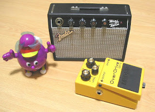
If i run it off a 9V adaptor, there's some pretty loud hum, so i just use a battery to power it and it's dead quiet. I know this is not a solution, but it may be the cause of your problem.
modman wrote: ↑ Let's hope it's not a hit, because soldering up the same pedal everyday, is a sad life. It's that same ole devilish double bind again...