biasing the Tillman Preamp
-
PaulBass

- Breadboard Brother
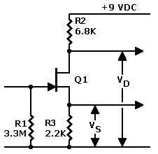
I made a preamp using the Tillman design and I used a 2SK117 instead of the J201. But I am getting distortion. So I am assuming the biasing resistors need to be changed. anybody know the suitable values for R2 & R3 for the 2SK117? or maybe the 2SK117 spec is way off 
-
RnFR
- Old Solderhand
Information
FETs vary wildly from one to the other, that is why i believe he says to try a number of them out in the article. if you don't have a lot of FETs, install a trimmer instead of R2 and adjust it until you get 4.5V-6V on the drain, using your ears for what sounds best.
"You've converted me to Cubic thinking. Where do I sign up for the newsletter? I need to learn more about how I can break free from ONEism Death Math." - Soulsonic
Blog-APOCALYPSE AUDIO
Blog-APOCALYPSE AUDIO
-
PaulBass
- Breadboard Brother
thanks, I measured the drain voltage and it was 8.5 voltsRnFR wrote:FETs vary wildly from one to the other, that is why i believe he says to try a number of them out in the article. if you don't have a lot of FETs, install a trimmer instead of R2 and adjust it until you get 4.5V-6V on the drain, using your ears for what sounds best.
-
RnFR
- Old Solderhand
Information
1/2 your supply voltage is always going to be the most headroom. so 4.5v if a 9v supply.PaulBass wrote:thanks, I measured the drain voltage and it was 8.5 voltsRnFR wrote:FETs vary wildly from one to the other, that is why i believe he says to try a number of them out in the article. if you don't have a lot of FETs, install a trimmer instead of R2 and adjust it until you get 4.5V-6V on the drain, using your ears for what sounds best.I was able to get it down between 5 - 7 volts using various resistors. Before I solder a permanent resistor, what would be the best voltage for headroom? Is 5 volts the best for maximum headroom? not much info on the web about 2SK117GR's
"You've converted me to Cubic thinking. Where do I sign up for the newsletter? I need to learn more about how I can break free from ONEism Death Math." - Soulsonic
Blog-APOCALYPSE AUDIO
Blog-APOCALYPSE AUDIO
-
roseblood11
- Tube Twister
In theory, you get the best headroom at Ub/2. But as mentioned above: Your ears decidePaulBass wrote:
thanks, I measured the drain voltage and it was 8.5 volts
-
PaulBass
- Breadboard Brother
got it, thanks!RnFR wrote:1/2 your supply voltage is always going to be the most headroom. so 4.5v if a 9v supply.PaulBass wrote:thanks, I measured the drain voltage and it was 8.5 voltsRnFR wrote:FETs vary wildly from one to the other, that is why i believe he says to try a number of them out in the article. if you don't have a lot of FETs, install a trimmer instead of R2 and adjust it until you get 4.5V-6V on the drain, using your ears for what sounds best.
-
PaulBass
- Breadboard Brother
I got the Vd on the 2SK117 to 4.7 volts and WOW! ![[smilie=a_happyhappy.gif]](./images/smilies/a_happyhappy.gif "a_happyhappy") It's like I'm playing a new bass. great headroom and clean fidelity. To my ears these 2SK117's sound a little better than the J201's. Although the J201's sound good also. thanks for all the help
It's like I'm playing a new bass. great headroom and clean fidelity. To my ears these 2SK117's sound a little better than the J201's. Although the J201's sound good also. thanks for all the help 
-
PaulBass
- Breadboard Brother
PaulBass wrote:I made a preamp using the Tillman design and I used a 2SK117 instead of the J201. But I am getting distortion. So I am assuming the biasing resistors need to be changed. anybody know the suitable values for R2 & R3 for the 2SK117? or maybe the 2SK117 spec is way off

Q1 2SK117
R1 500K
R2 6.8K
R3 130 Ohm (5K trimpot)
R4 50K pot
C1 47uf
C2 47uf
maybe changing some values will stop the clipping
-
RnFR
- Old Solderhand
Information
i would try some series resistance before the stage. anywhere between 10K-100K, but then you might want to raise that 500K back up so the input impedance doesn't get too low. that should help reduce the transient to something manageable. i believe that the preamp was initially made for piezo's, so your electric bass is probably putting out a bit too much signal than what the pre was designed for.
"You've converted me to Cubic thinking. Where do I sign up for the newsletter? I need to learn more about how I can break free from ONEism Death Math." - Soulsonic
Blog-APOCALYPSE AUDIO
Blog-APOCALYPSE AUDIO
-
RnFR
- Old Solderhand
Information
yup. right before bias resistor.. you could try a series pot set up like a variable resistor, with the input on lug 3, and the out on lugs 2 and 1 tied together, tune it to where you like it, then replace it with a resistor. or just keep the pot there so you can adjust the input for different guitars. you might have to add an input cap to keep the DC off of the pot though. are you getting scratchy noises when adjusting your volume control on the bass? sometimes you can get away without one when using FETs, but sometimes they do seem to cause problems as well. i'm not exactly sure of the specifics regarding that, though. probably should do a bit of reading up.
___________________
split topic.
___________________
split topic.
"You've converted me to Cubic thinking. Where do I sign up for the newsletter? I need to learn more about how I can break free from ONEism Death Math." - Soulsonic
Blog-APOCALYPSE AUDIO
Blog-APOCALYPSE AUDIO
-
fosnal1950
- Breadboard Brother
Try raising your V+ to 18 volt ( two batteries ) to give you more headroom.
-
RnFR
- Old Solderhand
Information
PaulBass wrote: I increased the power to 18v and it didn't help.
"You've converted me to Cubic thinking. Where do I sign up for the newsletter? I need to learn more about how I can break free from ONEism Death Math." - Soulsonic
Blog-APOCALYPSE AUDIO
Blog-APOCALYPSE AUDIO
-
earthtonesaudio
- Transistor Tuner
It's not a big deal, but 1/2 the supply voltage is not the highest-headroom bias point for a JFET. Think of it as a switch. With the switch open, the drain voltage can go up to the supply, but with it closed, it can only go down to Vsupply*[Rsource/(Rsource+Rdrain)], or about 2.5V. The midpoint between these two voltages is about 5.75V, and at most you're only going to get a +/-3.25V output swing, if the JFET swings symmetrically.
With a 6.5V p-p output available before clipping and a gain of about 3.1, the largest signal you can put in before distortion occurs is about 2.09V p-p. It is not only possible but likely that bass humbuckers are capable of putting out a larger p-p voltage than that.
If the main goal in using this circuit is the volume boost, a higher supply voltage is necessary (possibly even higher than 18V... I might try 24V or more if the JFET can take it).
On the other hand, if you don't need the boost and just like the way the JFET colors the sound, you can reduce the gain either using attenuation as suggested by RnFR, or by adjusting the ratio of drain and source resistors so Rd/Rs is a smaller number.
rocklander wrote:hairsplitting and semantics aren't exactly the same thing though.. we may need two contests for that.
-
bajaman

- Old Solderhand
Information
- Posts: 4549
- Joined: 26 Jun 2007, 21:18
- Location: New Brighton, Christchurch, NZ
- Has thanked: 596 times
- Been thanked: 2061 times
Just thought I would chime in here 
PaulBass has contacted me by PM seeking my help and I thought it may be relevant to others to share it here
If you look back in this thread you will see that he has reduced the source resistor to 130 ohms (5k trimpot) to bias the drain at half rail voltage.
Now with 6k8 drain and 130 ohm source resistors the fet has a signal voltage gain of 6k8/130 or 52.3 (over 34dB
  )
)
At this level of gain an input signal of 100 millivolts peak to peak is likely to clip the fet
PaulBass is looking for 3dB of boost - a very much lower than 34dB figure of gain, so I suggested that he use a 4k7 source load and an additional 3M3 biasing resistor connected from the +ve supply rail to the gate of the fet. It is now necessary to provide some dc voltage blocking at the gate of the fet - simply connect a 10n capacitor between the pickup output and the fet gate and the problem is solved.
ALSO - if extra gain is required, this can be achieved by connecting a suitable sized capacitor in parallel with the source resistor - for example 1uf ( this would give maximum gain down to 33Hz - -3db point). A smaller capacitor will roll of more low end and 10uf will take you down to 3.3Hz
To make this gain variable you could always connect a 50k trimpot in series with this capacitor (and connect the series combination of capacitor and trimpot in parallel with the 4k7 source resistor).
I hope these suggestions are of help to others here
cheers
bajaman
PaulBass has contacted me by PM seeking my help and I thought it may be relevant to others to share it here
If you look back in this thread you will see that he has reduced the source resistor to 130 ohms (5k trimpot) to bias the drain at half rail voltage.
Now with 6k8 drain and 130 ohm source resistors the fet has a signal voltage gain of 6k8/130 or 52.3
At this level of gain an input signal of 100 millivolts peak to peak is likely to clip the fet
PaulBass is looking for 3dB of boost - a very much lower than 34dB figure of gain, so I suggested that he use a 4k7 source load and an additional 3M3 biasing resistor connected from the +ve supply rail to the gate of the fet. It is now necessary to provide some dc voltage blocking at the gate of the fet - simply connect a 10n capacitor between the pickup output and the fet gate and the problem is solved.
ALSO - if extra gain is required, this can be achieved by connecting a suitable sized capacitor in parallel with the source resistor - for example 1uf ( this would give maximum gain down to 33Hz - -3db point). A smaller capacitor will roll of more low end and 10uf will take you down to 3.3Hz
To make this gain variable you could always connect a 50k trimpot in series with this capacitor (and connect the series combination of capacitor and trimpot in parallel with the 4k7 source resistor).
I hope these suggestions are of help to others here
cheers
bajaman
be kind to all animals - especially human beings
-
earthtonesaudio
- Transistor Tuner
I missed that, thanks for pointing out that he had changed the values. But when I look at his post now it says the drain resistor is 130 ohms and the source is 6.8k, and his drain voltage is 9V. This is reversed from what you said, and I have to wonder if PaulBass has something wired wrong. The small drain resistor and large source resistor makes his 9V drain measurement plausible, and certainly wouldn't sound right. Maybe he make the source voltage 4.5V instead of the drain?bajaman wrote:Just thought I would chime in here
If you look back in this thread you will see that he has reduced the source resistor to 130 ohms (5k trimpot) to bias the drain at half rail voltage.
Now with 6k8 drain and 130 ohm source resistors the fet has a signal voltage gain of 6k8/130 or 52.3
At this level of gain an input signal of 100 millivolts peak to peak is likely to clip the fet
rocklander wrote:hairsplitting and semantics aren't exactly the same thing though.. we may need two contests for that.
-
PaulBass
- Breadboard Brother
drain to ground reads 9v. 2SK117 is DGS. 18v is going to 6K8 going to D. pickup input is going to grounded 500K resistor to G. S is going to 130R (from 5K trimpot) to output cap to output jack. I think bajaman has the solution, I'm going to try thatearthtonesaudio wrote:I missed that, thanks for pointing out that he had changed the values. But when I look at his post now it says the drain resistor is 130 ohms and the source is 6.8k, and his drain voltage is 9V. This is reversed from what you said, and I have to wonder if PaulBass has something wired wrong. The small drain resistor and large source resistor makes his 9V drain measurement plausible, and certainly wouldn't sound right. Maybe he make the source voltage 4.5V instead of the drain?bajaman wrote:Just thought I would chime in here
If you look back in this thread you will see that he has reduced the source resistor to 130 ohms (5k trimpot) to bias the drain at half rail voltage.
Now with 6k8 drain and 130 ohm source resistors the fet has a signal voltage gain of 6k8/130 or 52.3
At this level of gain an input signal of 100 millivolts peak to peak is likely to clip the fet
-
PaulBass
- Breadboard Brother
after trying out different components I found a combination that reduced the clipping to almost nothing. I put 2 x 2.2M parallel resistors in front of R1 and kept R1 at 500K, the sum of that makes 350K going into the gate. I got rid of one of the batteries and adjusted the Vd to 4.5v. now I only get barely audible soft clipping when both pickups are together in series mode. I have to play really hard to hear it. when I play normal the signal is clean. that horrible clipping distortion is gone.
![[smilie=orange.gif]](./images/smilies/Orange.gif "Orange")
-
RnFR
- Old Solderhand
Information
nice catch bajaman! i didn't realize that he was biasing from the source. a higher source resistance could definitely help. that way you would probably reduce noise, too. an input cap is usually a good idea as well. 
"You've converted me to Cubic thinking. Where do I sign up for the newsletter? I need to learn more about how I can break free from ONEism Death Math." - Soulsonic
Blog-APOCALYPSE AUDIO
Blog-APOCALYPSE AUDIO
-
PaulBass
- Breadboard Brother
thanks for the reminder. I forgot bajaman mentioned raising the source resistance. I raised it and now the clipping totally gone! Now I have a clean signal!RnFR wrote:nice catch bajaman! i didn't realize that he was biasing from the source. a higher source resistance could definitely help. that way you would probably reduce noise, too. an input cap is usually a good idea as well.
Q1 2SK117
R0 1M (2 x 2M in parallel)
R1 500K
R2 22.1K
R3 1.5K (5K trimpot)
R4 50K pot
C1 47uf
C2 47uf
It was a PITA to bias this thing but I see why Roland/Boss used these transistors a lot, great clean transparent sound. looks like I "engineered" my first preamp
thanks for the help, you guys rule