3PDT Bypass Switch Wiring

All frequent questions on switching: true or not true bypass, transistor-based or mechanical.
Post Reply
User avatar
ChrisFFTA
Breadboard Brother
Information
Posts: 99
Joined: 30 Dec 2007, 07:43
Been thanked: 3 times

Post by ChrisFFTA »

Igloo wrote:For a bit of fun
Factory de Fuzz vero layout
hi there

i am new to this forum and new(ish) to DIY... so pls excuse my ignorance with the following q's:

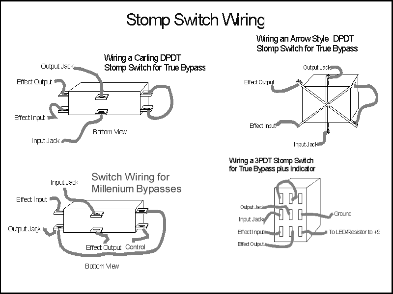
1) in this vero layout, where is the switch? and where does it wire up to?
2) the in and out... there is only one wire... shouldnt there be two?
3) also only one wire is there for the (v. i assume the other one goes to somewhere on the switch?

again my apologies for noobie q's

chris

User avatar
briggs
Tube Twister
Information
Posts: 1971
Joined: 12 Jul 2007, 10:02
my favorite amplifier: Briggs Custom Suprono
Completed builds: Too many to still class myself as sane....
Location: Breaking into Heaven.
Has thanked: 27 times
Been thanked: 128 times
Contact:

Post by briggs »

Hey there, for all you wiring queries there is a great article over here: http://www.generalguitargadgets.com/ind ... &Itemid=27

Check out those articles, they should point you in the right direction 8)
Image

I am Klon.

User avatar
ChrisFFTA
Breadboard Brother
Information
Posts: 99
Joined: 30 Dec 2007, 07:43
Been thanked: 3 times

Post by ChrisFFTA »

thx for that link briggs but naturally i have another q...

with the 3PDT switch it mentions wires to output/input jack and effect input/output... whats the difference?

User avatar
briggs
Tube Twister
Information
Posts: 1971
Joined: 12 Jul 2007, 10:02
my favorite amplifier: Briggs Custom Suprono
Completed builds: Too many to still class myself as sane....
Location: Breaking into Heaven.
Has thanked: 27 times
Been thanked: 128 times
Contact:

Post by briggs »

ah, You have one wire from the input jack of the fx to the switch, then one from the switch to the actual input of the FX circuit. You also have a wire from the output of the actual circuit to the switch then from the switch to the output jack.

See crappy diagram of dpdt switch:

to fx circuit board input ------------O O------------- from fx circuit board output
--------from input jack --------------O O------------- to output jack
these two are connected----------O-O
Image

I am Klon.

User avatar
ChrisFFTA
Breadboard Brother
Information
Posts: 99
Joined: 30 Dec 2007, 07:43
Been thanked: 3 times

Post by ChrisFFTA »

briggs wrote:ah, You have one wire from the input jack of the fx to the switch, then one from the switch to the actual input of the FX circuit. You also have a wire from the output of the actual circuit to the switch then from the switch to the output jack.

See crappy diagram of dpdt switch:

to fx circuit board input ------------O O------------- from fx circuit board output
--------from input jack --------------O O------------- to output jack
these two are connected----------O-O
aha... cheers again.

hoping to throw an led into this one as well...

User avatar
ChrisFFTA
Breadboard Brother
Information
Posts: 99
Joined: 30 Dec 2007, 07:43
Been thanked: 3 times

Post by ChrisFFTA »

ok saga continues... is this the correct wiring diagram for LED but no DC? in the diagram the pins on the switch are horizontal... shouldnt they be vertical? some diagrams are hori others vert...

http://www.generalguitargadgets.com/dia ... attery.gif

Thanks again

User avatar
R.G.
Resistor Ronker
Information
Posts: 337
Joined: 22 Sep 2007, 02:24
Been thanked: 39 times

Post by R.G. »


Post Reply