Page 1 of 1
RC filters! Help me understand it.
Posted: 09 May 2013, 05:42
by piod
Many effects are include RC filters. Help me understand it, please.
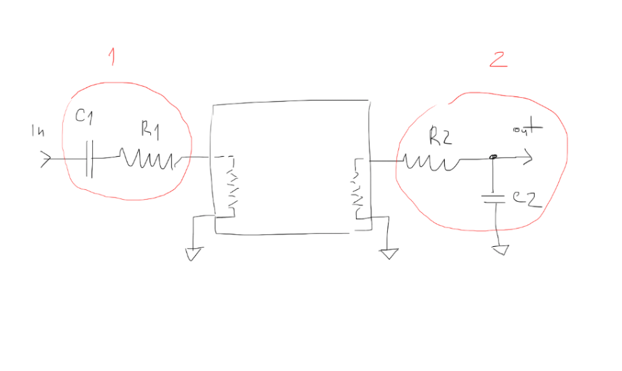
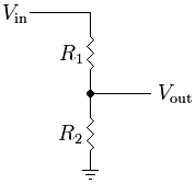
Is there area №1 its a high-pass filter? If this is true, why resistor R1 is in series with the capacitor?
How to calculate cut-off frequency?

Is this true?
Area №2 its a Low-pass filter i understand it.
Thanks!
Re: RC filters! Help me understand it.
Posted: 09 May 2013, 15:36
by Lucifer
In a very simple nutshell, without going into the actual physics and maths of their behaviour, capacitors 'pass' high frequencies and resist low frequencies.
It's easy to remember which way round that is, if you bear in mind that caps are open circuit to DC, which is 0Hz - so low frequencies - which are nearer DC than high frequencies, have difficulty getting through, while the high frequences get through more easily.
So, looking at part 1 of the circuit, high frequencies will be allowed to pass through the cap - so the circuit is a High Pass filter.
The reistor in series with the cap forms a potential divider with the input impedance of the amp/pedal/whatever, reducing the input level to prevent overload, etc.
In circuit 2, the cap passes high frequencies to ground (you could call it a High Pass to Ground) while the lower frequencies are ignored by the cap and pass onto the next circuit along - so Circuit 2 is a Low Pass filter (which you understand already).
The formula is correct, and can be applied to both types of filter.
Re: RC filters! Help me understand it.
Posted: 09 May 2013, 18:56
by juanro
The formula involving both R and C, if I remember correctly, is where the impedance (resistance, meh) of the capacitor equals that of the resistor. You can use a similar formula without R to find the impedance (again: resistance) of the capacitor at a given frequency.
The corner frequency (when it pass -3db, or half the input voltaje) of the high pass at the input should take in account the (possibly unkown) input impedance (I don't get tired of saying it: resistance) of the middle block. R1 in series with the capacitor provides a limit to the max ammount of highs it will pass.
Set up a little Excel with the formula for capacitor impedance Z = 1/2*pi*f*C and include that in some more formulas for various resistive dividers, play with the "f" value (the only variable you will have) and you'll get a hold pretty quick on what's going on.
Regards
Juanro
Re: RC filters! Help me understand it.
Posted: 09 May 2013, 19:35
by piod
Lucifer wrote:In a very simple nutshell, without going into the actual physics and maths of their behaviour, capacitors 'pass' high frequencies and resist low frequencies.
It's easy to remember which way round that is, if you bear in mind that caps are open circuit to DC, which is 0Hz - so low frequencies - which are nearer DC than high frequencies, have difficulty getting through, while the high frequences get through more easily.
So, looking at part 1 of the circuit, high frequencies will be allowed to pass through the cap - so the circuit is a High Pass filter.
The reistor in series with the cap forms a potential divider with the input impedance of the amp/pedal/whatever, reducing the input level to prevent overload, etc.
In circuit 2, the cap passes high frequencies to ground (you could call it a High Pass to Ground) while the lower frequencies are ignored by the cap and pass onto the next circuit along - so Circuit 2 is a Low Pass filter (which you understand already).
The formula is correct, and can be applied to both types of filter.
Thanks for the clarification. My experiments with the oscilloscope and generator showed that the circuit 1 operates as a limitation, you're right. It worked like a valve limiting the frequency over a range, but it did not work as a filter with a cut-off point.
Then I used a capacitor and a resistor in parallel with the input and it worked great with a cut-off point.
I calculated parameters of the capacitor and resistor at a frequency of about 350-400 Hz. I observed an increase in amplitude frequency slice occurred before or after, depending on the filter type. I tried to filter high frequency and low frequency in the classic turn.
Re: RC filters! Help me understand it.
Posted: 09 May 2013, 21:25
by apollomusicservice
RC circuit is a bit like oscillatory circuit that provide band pass (oposite of bandpass is bandstop-notch filter) guarded inability to pass DC current (C) and ultra-high frequencies, and as such ensures that the output voltage does not depend on frequency.
RC gate has a capacitive reactance [img]reactance.gif[/img]
and total impedance (apparent resistivity at certain frequencies) [img]impedance.gif[/img]
Replacement frequency in the pattern can be calculated how much "resistance" RC circuit provide for given values.
This is a simplified explanation because we did not turn on a very important inductive component contained in pickup on input of circuit.
Re: RC filters! Help me understand it.
Posted: 30 Aug 2013, 01:22
by commathe