Question about wiring true bypass + LED into this Verolayout
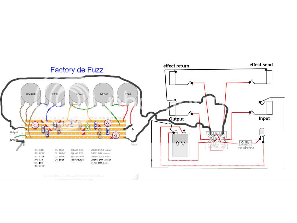
This is my first build, and I can for the life of me find information about this stage of the wiring. Read plenty about the pros and cons of true bypass etc. - but not how Input and output stages are separated or anything helpful!
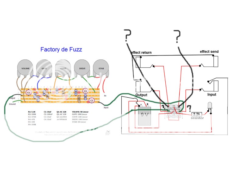
So can someone explain where the effect return and send are on the vero layout so that I can wire the 3PDT switch onto the circuit correctly?
Thanks
Ok been puzzling over this for a while, and think I understand how it works now - can you have a look at this:
Is the wiring correct?
Does the ground go to the negative part of the battery?
I've had to adapt it a little to fit a 3TDP switch for an LED
Is the wiring correct?
Does the ground go to the negative part of the battery?
I've had to adapt it a little to fit a 3TDP switch for an LED