Voltage Doubler using NE555 timer

Frequent asked about building blocks: gain stages, buffers, clipping configurations, ...
Post Reply
User avatar
cacophony
Breadboard Brother
Information
Posts: 57
Joined: 20 Jan 2009, 06:36

Post by cacophony »

Hi guys! I'm just wondering if this schematic I made through EAGLE CAD is the same as the one posted at http://www.elecfree.com/electronic/volt ... th-ic-555/ Image

I find the schematic posted at the said website unclear enough.

Thanks.

User avatar
modman
a d m i n
Information
Posts: 4897
Joined: 19 Jun 2007, 16:57
Has thanked: 4411 times
Been thanked: 2139 times

Post by modman »

Also have a look here:
viewtopic.php?f=13&t=80&
Please, support freestompboxes.org on Patreon for just 1 pcb per year! Or donate directly through PayPal

User avatar
JiM
Diode Debunker
Information
Posts: 967
Joined: 11 Mar 2008, 22:56
Completed builds: Completed builds :
Proco Rat
MXR MicroAmp in a volume pedal
TubeDriver (w/ NoS russian tube and big muff tone contol) + Phase 45 (w/ univibe cap ratio)
Dallas Rangemaster (w/ noisy OC75, negative ground)
SubCaster tube booster (w/ NoS russian tube, PtP)
Hot Harmonics
Music From Outer Space SubCommander in progress
Crackle Not OK
Simple bass blender in a 1590A
Bazz Fuss with a photo-darlington
Location: France
Has thanked: 70 times
Been thanked: 66 times
Contact:

Post by JiM »

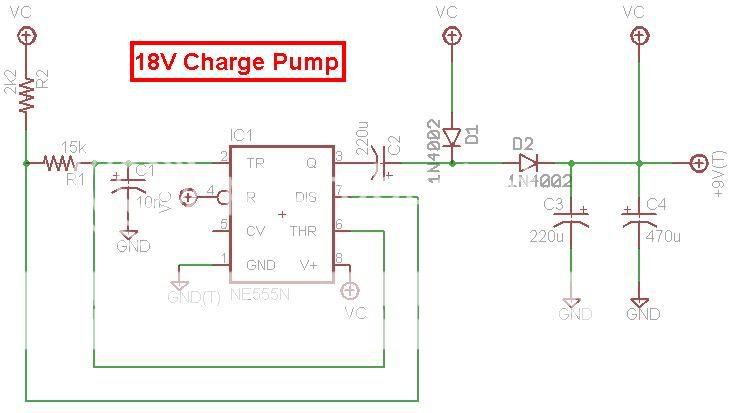
There shall be no connection between C4 and the output voltage ! You're shorting it to Vcc, defeating the purpose of the circuit.
I agree it's not easy to see in the original schematic that there is NO dot where these wires cross ...
I only give negative feedback.

User avatar
earthtonesaudio
Transistor Tuner
Information
Posts: 1244
Joined: 28 Jan 2008, 04:00
Completed builds: Metal Simplex, Fuzz Factory, two Fab Echos-modded, Noisy Cricket, Earth & Space Wah, TS-7-modded, passive xover/splitter box, opamp fuzz
Location: Bloomington, Indiana
Has thanked: 11 times
Been thanked: 75 times

Post by earthtonesaudio »

Ah! Good call, JiM. I glanced here earlier but failed to spot that! I agree, C4 should connect to the main supply only, not to the boosted voltage. It would be even better to show it directly across pins 1 and 8 of the 555, because it should be as close as possible to that IC in the board layout.
One more thing, it wouldn't hurt to add the typical .01u cap from pin 5 (CV) to ground.
rocklander wrote:hairsplitting and semantics aren't exactly the same thing though.. we may need two contests for that.

User avatar
cacophony
Breadboard Brother
Information
Posts: 57
Joined: 20 Jan 2009, 06:36

Post by cacophony »

earthtonesaudio wrote:Ah! Good call, JiM. I glanced here earlier but failed to spot that! I agree, C4 should connect to the main supply only, not to the boosted voltage. It would be even better to show it directly across pins 1 and 8 of the 555, because it should be as close as possible to that IC in the board layout.
One more thing, it wouldn't hurt to add the typical .01u cap from pin 5 (CV) to ground.
what does the 0.01 uf cap do to the timer?

User avatar
earthtonesaudio
Transistor Tuner
Information
Posts: 1244
Joined: 28 Jan 2008, 04:00
Completed builds: Metal Simplex, Fuzz Factory, two Fab Echos-modded, Noisy Cricket, Earth & Space Wah, TS-7-modded, passive xover/splitter box, opamp fuzz
Location: Bloomington, Indiana
Has thanked: 11 times
Been thanked: 75 times

Post by earthtonesaudio »

Reduces noise/false triggering when using a bipolar 555. It may not be necessary, but it wouldn't hurt anything to include it.
rocklander wrote:hairsplitting and semantics aren't exactly the same thing though.. we may need two contests for that.

Post Reply