IC question

All frequent questions about ICs of all kinds, will be stored here.
User avatar
Mr. G.
Resistor Ronker
Information
Posts: 384
Joined: 03 Jul 2008, 19:32
my favorite amplifier: Undecided
Completed builds: 3-loop + tuner out TB loop pedal
Eternity overdrive (Deaj perf layout)
YATS (many)
BOR
DLS
COT (Briggs mods)
Crunchbox
SHO (several)
Fuzz Factory
Several LM386 based distortions
Location: Nova Scotia, Canada
Has thanked: 1 time
Been thanked: 9 times

Post by Mr. G. »

I've got a question about ICs, like the JRC4558 for a common example... In a tubescreamer style circuit, does it matter which op amp is used for the clipping section, and which is used for an active tone section or an extra boost section? I've seen them both ways and was just wondering if there was a reason other than whichever works best for the PCB layout.

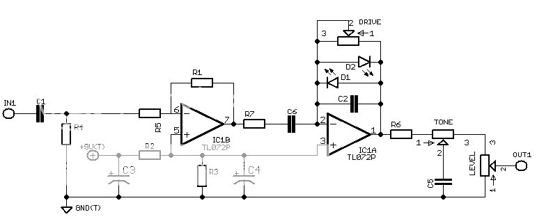
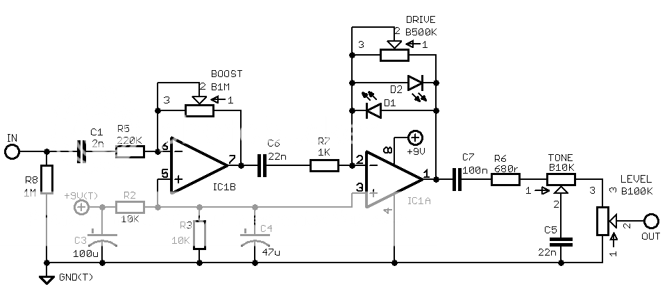
Second, I've been wanting to play around a simple circuit like the HAO Rust Driver, and use the first op-amp as a booster, but with a HPF in front of it, and the second op-amp would be set up similar to a tubescreamer. Here's what I've got so far, schematic wise: https://i2.photobucket.com/albums/y50/P ... Rusty2.png

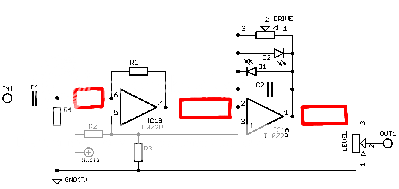
I'm unsure of what, if anything, should go in the highlighted sections. I'll probably want to add some sort of treble roll off tone section somewhere in there too.

What would be a good starting value for the resistor in the boost section between pins 6 & 7?

The reason I"m doing this is because I like how the Rust Driver sounds, but I would like for the gain to be adjustable, and I would also like to shape the frequency response of the boost more to my tastes. The way I would describe the sound I'm after would be something like a Crunchbox being boosted by an SD-1 to tighten things up.

Am I on the right track with how to achieve my goal, or am I going to be way off? :hmmm:

User avatar
JiM
Diode Debunker
Information
Posts: 967
Joined: 11 Mar 2008, 22:56
Completed builds: Completed builds :
Proco Rat
MXR MicroAmp in a volume pedal
TubeDriver (w/ NoS russian tube and big muff tone contol) + Phase 45 (w/ univibe cap ratio)
Dallas Rangemaster (w/ noisy OC75, negative ground)
SubCaster tube booster (w/ NoS russian tube, PtP)
Hot Harmonics
Music From Outer Space SubCommander in progress
Crackle Not OK
Simple bass blender in a 1590A
Bazz Fuss with a photo-darlington
Location: France
Has thanked: 70 times
Been thanked: 66 times
Contact:

Post by JiM »

Mr. G. wrote:does it matter which op amp is used for the clipping section, and which is used for an active tone section
They shall be exactly the same, as they share the same silicon chip : same lithography masks, same impurities, same tolerances, same temperature, same power supply ... In fact the silicon layout is often symetrical.
Mr. G. wrote:I'm unsure of what, if anything, should go in the highlighted sections.
You need at least some DC blocking caps, as the opamps are referenced to Vcc/2.
I'd start with the Rusty Driver values on breadboard or simulation (like LTSpice), and tweak from that.
Mr. G. wrote:The reason I"m doing this is because I like how the Rust Driver sounds, but I would like for the gain to be adjustable, and I would also like to shape the frequency response of the boost more to my tastes.
For the adjustable gain, you've got it. To shape a bit the booster response, you could swap values for the input cap. Or put a LPF in the feedback loop for something more drastic.
Mr. G. wrote:The way I would describe the sound I'm after would be something like a Crunchbox being boosted by an SD-1 to tighten things up.
Then go for it ! :mrgreen:
I only give negative feedback.

User avatar
Mr. G.
Resistor Ronker
Information
Posts: 384
Joined: 03 Jul 2008, 19:32
my favorite amplifier: Undecided
Completed builds: 3-loop + tuner out TB loop pedal
Eternity overdrive (Deaj perf layout)
YATS (many)
BOR
DLS
COT (Briggs mods)
Crunchbox
SHO (several)
Fuzz Factory
Several LM386 based distortions
Location: Nova Scotia, Canada
Has thanked: 1 time
Been thanked: 9 times

Post by Mr. G. »

Thanks for the info JiM! I kinda figured both opamps were the same. Thanks for confirming this.

I'll have to do some more research on the DC blockage.

Will adjusting the value of R1 change the amount of boost? I'm assuming it will, but I'm unsure of how to calculate how much boost I'll get.

One last question... what exactly is the feedback loop? :oops: I've heard it referred to a lot, but still haven't figured out what this means.

User avatar
lolbou
Old Solderhand
Information
Posts: 2617
Joined: 18 Nov 2008, 21:38
Has thanked: 308 times
Been thanked: 225 times

Post by lolbou »

The feedback loop is the circuitry linking the output and the inverting input of the opamp... It makes it operate in a linear way (if not, the opamp can only deliver + or - Vcc)...
- Are you a mod or a rocker?
- Uh, no, I'm a mocker.

User avatar
Mr. G.
Resistor Ronker
Information
Posts: 384
Joined: 03 Jul 2008, 19:32
my favorite amplifier: Undecided
Completed builds: 3-loop + tuner out TB loop pedal
Eternity overdrive (Deaj perf layout)
YATS (many)
BOR
DLS
COT (Briggs mods)
Crunchbox
SHO (several)
Fuzz Factory
Several LM386 based distortions
Location: Nova Scotia, Canada
Has thanked: 1 time
Been thanked: 9 times

Post by Mr. G. »

So the feedback loop would be between pins 7 and 2 on the schematic I posted in my first post?

User avatar
lolbou
Old Solderhand
Information
Posts: 2617
Joined: 18 Nov 2008, 21:38
Has thanked: 308 times
Been thanked: 225 times

Post by lolbou »

That's it. You could change the frequency response in that first opamp.

Add a cap in parallel to R1 to make the roll off frequency higher.

ps: you don't want any boost level control?
- Are you a mod or a rocker?
- Uh, no, I'm a mocker.

User avatar
JiM
Diode Debunker
Information
Posts: 967
Joined: 11 Mar 2008, 22:56
Completed builds: Completed builds :
Proco Rat
MXR MicroAmp in a volume pedal
TubeDriver (w/ NoS russian tube and big muff tone contol) + Phase 45 (w/ univibe cap ratio)
Dallas Rangemaster (w/ noisy OC75, negative ground)
SubCaster tube booster (w/ NoS russian tube, PtP)
Hot Harmonics
Music From Outer Space SubCommander in progress
Crackle Not OK
Simple bass blender in a 1590A
Bazz Fuss with a photo-darlington
Location: France
Has thanked: 70 times
Been thanked: 66 times
Contact:

Post by JiM »

Mr. G. wrote:So the feedback loop would be between pins 7 and 2 on the schematic I posted in my first post?
No, it's the link between the output and the inverting input of the same opamp.
In your schematic, the feedback loop of the first opamp is R1, and the feedback loop of the second opamp is a cap, two leds and a pot all in parallel.

To be precise, we should talk about negative feedback (because it's going back to the inverting input), if it were positive feedback it would lead to oscillation (resonnance, larsen, you name it).
What is interesting about negative feedback, is that what happens inside is approximately the opposite of what happens in the normal signal path. For example, if you put a low-pass filter in the feedback loop, the result is a hi-pass filter. If you increase the resistance in the feedback loop, you increase the gain. There are "negative resistance" circuit, or the "gyrator" who makes a virtual inductor out of a cap (look at a Boss GE-7). Diodes makes it a logarithmic amplifier.
And as Lolbou said NFB is mostly used to reduce non-linearities of amplifiers, at the expense of some gain. But opamps have so much gain that they need it anyway, otherwise they clip immediately.

More info : http://en.wikipedia.org/wiki/Negative_f ... _amplifier
http://en.wikipedia.org/wiki/Operationa ... e_feedback
I only give negative feedback.

User avatar
Mr. G.
Resistor Ronker
Information
Posts: 384
Joined: 03 Jul 2008, 19:32
my favorite amplifier: Undecided
Completed builds: 3-loop + tuner out TB loop pedal
Eternity overdrive (Deaj perf layout)
YATS (many)
BOR
DLS
COT (Briggs mods)
Crunchbox
SHO (several)
Fuzz Factory
Several LM386 based distortions
Location: Nova Scotia, Canada
Has thanked: 1 time
Been thanked: 9 times

Post by Mr. G. »

Thanks for clarifying! Looks like I've got some researching and studying ahead of me. Thanks for the links. That looks like a good place to start.

User avatar
lolbou
Old Solderhand
Information
Posts: 2617
Joined: 18 Nov 2008, 21:38
Has thanked: 308 times
Been thanked: 225 times

Post by lolbou »

JiM wrote:No, it's the link between the output and the inverting input of the same opamp.
Sorry about that, Mr G wrote 7 and 2, and I read 7 and 6... I was really talking about R1, but my answer did cause some misunderstanding... :slap:

This proves again that the more people here, the exacter and merrier!! :wink:
- Are you a mod or a rocker?
- Uh, no, I'm a mocker.

User avatar
Mr. G.
Resistor Ronker
Information
Posts: 384
Joined: 03 Jul 2008, 19:32
my favorite amplifier: Undecided
Completed builds: 3-loop + tuner out TB loop pedal
Eternity overdrive (Deaj perf layout)
YATS (many)
BOR
DLS
COT (Briggs mods)
Crunchbox
SHO (several)
Fuzz Factory
Several LM386 based distortions
Location: Nova Scotia, Canada
Has thanked: 1 time
Been thanked: 9 times

Post by Mr. G. »

How does the schematic look now?

Image

User avatar
lolbou
Old Solderhand
Information
Posts: 2617
Joined: 18 Nov 2008, 21:38
Has thanked: 308 times
Been thanked: 225 times

Post by lolbou »

Good to me. But what values do you expect for R6? Actually, I would not have use this one at first. What led you to this choice?
- Are you a mod or a rocker?
- Uh, no, I'm a mocker.

User avatar
JiM
Diode Debunker
Information
Posts: 967
Joined: 11 Mar 2008, 22:56
Completed builds: Completed builds :
Proco Rat
MXR MicroAmp in a volume pedal
TubeDriver (w/ NoS russian tube and big muff tone contol) + Phase 45 (w/ univibe cap ratio)
Dallas Rangemaster (w/ noisy OC75, negative ground)
SubCaster tube booster (w/ NoS russian tube, PtP)
Hot Harmonics
Music From Outer Space SubCommander in progress
Crackle Not OK
Simple bass blender in a 1590A
Bazz Fuss with a photo-darlington
Location: France
Has thanked: 70 times
Been thanked: 66 times
Contact:

Post by JiM »

That's better !
Just a few more ideas :
  • C1 will pop when switching on, if left like that. If R4 is intended as a big pull-down resistor (about 1meg), then C1 should be between R4 and R5.
  • You need another cap before R6, to block DC. You know, an opamp works with bipolar supply, but in stompboxes it's easier to use only one battery. So they usually work with +4.5V / -4.5V supplies, referenced to Vcc/2. Which is the same as +9V / 0V referenced to ground, but then you signal is shifted by +4.5V : hence the need for DC blocking caps. I'm not sure the explaination is clear ...
  • Obviously R2 = R3 to get Vcc/2. 10k is a standard value.
  • You can make R1 a pot (wired as variable resistor) to change the gain of the booster
lolbou wrote:Good to me. But what values do you expect for R6? Actually, I would not have use this one at first. What led you to this choice?
Isn't it the Stupidly Wonderful Tone Control ?
http://hammer.ampage.org/files/SWTC.gif
I only give negative feedback.

User avatar
lolbou
Old Solderhand
Information
Posts: 2617
Joined: 18 Nov 2008, 21:38
Has thanked: 308 times
Been thanked: 225 times

Post by lolbou »

Putainnnn... I meant R7... :slap: :slap: :slap: :slap: :slap: :slap: :slap:

I think I'm about to print the schems in the future so that I can be good at naming components... :roll: But I have a strong beer-headache today, which makes my own biasing faulty... :lol:

And still no cap across R1?

So, to get back to these resistors, why R7? No current is flowing in it, so what's its purpose?
- Are you a mod or a rocker?
- Uh, no, I'm a mocker.

User avatar
Mr. G.
Resistor Ronker
Information
Posts: 384
Joined: 03 Jul 2008, 19:32
my favorite amplifier: Undecided
Completed builds: 3-loop + tuner out TB loop pedal
Eternity overdrive (Deaj perf layout)
YATS (many)
BOR
DLS
COT (Briggs mods)
Crunchbox
SHO (several)
Fuzz Factory
Several LM386 based distortions
Location: Nova Scotia, Canada
Has thanked: 1 time
Been thanked: 9 times

Post by Mr. G. »

JiM wrote:That's better !
Just a few more ideas :
  • C1 will pop when switching on, if left like that. If R4 is intended as a big pull-down resistor (about 1meg), then C1 should be between R4 and R5.
C1 and R4 are intended to be a HPF to kill some of the bass before it gets boosted. I'm not really sure what R5 is for. It was in the rust driver schematic and it was in one of the diagrams in one of the links you posted. I would probably add a 1M pull-down resistor before C1, if it needs one.
[*]You need another cap before R6, to block DC. You know, an opamp works with bipolar supply, but in stompboxes it's easier to use only one battery. So they usually work with +4.5V / -4.5V supplies, referenced to Vcc/2. Which is the same as +9V / 0V referenced to ground, but then you signal is shifted by +4.5V : hence the need for DC blocking caps. I'm not sure the explaination is clear ...
Should this be an electrolytic, or could it be something like a 1uF box type cap? Also, would it go to ground, or would it be in series with R6?
[*]Obviously R2 = R3 to get Vcc/2. 10k is a standard value.[/list]
I know the Vout would still be 4.5v, but would there be any difference between using two 100k resistors as opposed to using two 10k resistors?
Isn't it the Stupidly Wonderful Tone Control ?
http://hammer.ampage.org/files/SWTC.gif
Why yes it is :)

User avatar
Mr. G.
Resistor Ronker
Information
Posts: 384
Joined: 03 Jul 2008, 19:32
my favorite amplifier: Undecided
Completed builds: 3-loop + tuner out TB loop pedal
Eternity overdrive (Deaj perf layout)
YATS (many)
BOR
DLS
COT (Briggs mods)
Crunchbox
SHO (several)
Fuzz Factory
Several LM386 based distortions
Location: Nova Scotia, Canada
Has thanked: 1 time
Been thanked: 9 times

Post by Mr. G. »

lolbou wrote:And still no cap across R1?

So, to get back to these resistors, why R7? No current is flowing in it, so what's its purpose?
None of the schematics I've seen that use half of the IC as a boost have had a cap.

R7 and C6 are there because that's how they are on the Rust Driver schematic. No idea what they are for, unless they act as a LPF. I would think C6 would need to go to ground if that were the case though. :scratch:

User avatar
lolbou
Old Solderhand
Information
Posts: 2617
Joined: 18 Nov 2008, 21:38
Has thanked: 308 times
Been thanked: 225 times

Post by lolbou »

Mr. G. wrote:I'm not really sure what R5 is for.
R5 sets the gain (Gain = - R1/R5) of the boost section along with R1 (that JiM suggested to be a pot to have a variable gain).
Mr. G. wrote:Should this be an electrolytic, or could it be something like a 1uF box type cap? Also, would it go to ground, or would it be in series with R6?
I'd rather go for a film one in series between pin 1 and R6. And no, you shouldn't lead it to ground, because it's here to block the DC from the output.
Mr. G. wrote:I know the Vout would still be 4.5v, but would there be any difference between using two 100k resistors as opposed to using two 10k resistors?
From a voltage point of view, it's the same. You can adjust your values with the capacitors to get some filtering of your DC supply.
- Are you a mod or a rocker?
- Uh, no, I'm a mocker.

User avatar
briggs
Tube Twister
Information
Posts: 1971
Joined: 12 Jul 2007, 10:02
my favorite amplifier: Briggs Custom Suprono
Completed builds: Too many to still class myself as sane....
Location: Breaking into Heaven.
Has thanked: 27 times
Been thanked: 128 times
Contact:

Post by briggs »

OK OK OK! Hao Rust Driver, now here is an interesting little circuit.

You could use any cap, the smaller the cap the harder the lower frequencies will have to work to get through; check AG's very useful chart - http://analogguru.an.ohost.de/techstuff/Reactance.htm That chart can be very useful for playing with simple RC boost/cut circuits. The cap would simple go between the output of the op amp and R6. This cap stops the DC voltage on the opamp output from getting into those pots and causing crackle when you turn them. Capacitors allow AC current to flow but will block any added DC (Which is added during the amp stage).

You can use any equal value resistors to get Vr 1/2v whatever. I like to use slightly off balance values to introduce some asymmetric clipping in my op amp circuits. Smaller values will be very slightly less noisy but they will increase current consumption.

With the way you have the opamps orientated you are using them as "inverting" op amps. Whereby any signal which enters the opamp comes out the other end 180 degrees inverted, a sort of mirror image if you will. Running two in series means that the signal stays "in phase" as it is inverted twice. R5 & R1 combine to set gain in the first stage - gain is calculated; Vg = R1/R5. In an inverting set up (unlike a Tubescreamer which is none inverting) C1 & R5 combine to create a HPF, the corner frequency which can be determined with; F = 1/(2pi*C*R).

Loubou is suggesting that R7 & C6 need to be swapped around in order, C6 should become before R7. The same calculations would apply for the second stage. Placing a Cap in the feedback loop will roll off high freqs. Use the formula presented earlier and use C2 as you "C" value and the Drive pot value (at various points on it's travel) as your "R", as you can see more freqs are rolled off as gain increases.

edit - R5 would set the input impedance of the circuit..
Image

I am Klon.

User avatar
Mr. G.
Resistor Ronker
Information
Posts: 384
Joined: 03 Jul 2008, 19:32
my favorite amplifier: Undecided
Completed builds: 3-loop + tuner out TB loop pedal
Eternity overdrive (Deaj perf layout)
YATS (many)
BOR
DLS
COT (Briggs mods)
Crunchbox
SHO (several)
Fuzz Factory
Several LM386 based distortions
Location: Nova Scotia, Canada
Has thanked: 1 time
Been thanked: 9 times

Post by Mr. G. »

Here's my updated schematic, with starting point values:

Image

If I'm understanding correctly, R5 does a lot. It sets the input impedance, sets the gain of the boost along with the boost pot, and acts as a HPF along with C1. :shock:

Since the signal is inverted after the first stage, would C6 and R7 act as a LPF instead of a HPF according to their current orientation?

Lastly, I removed the cap across pins 2 & 1 since I've got an adjustable LPF on the output. Would it be better to leave it there, and use a small value such as a 51p?

The HAO Rust Driver really is a cool and good sounding circuit. I just can't help but feel that it can sound better and be more versatile (at least for my needs/wants, that is).

Thanks for all the help and info guys!

User avatar
JiM
Diode Debunker
Information
Posts: 967
Joined: 11 Mar 2008, 22:56
Completed builds: Completed builds :
Proco Rat
MXR MicroAmp in a volume pedal
TubeDriver (w/ NoS russian tube and big muff tone contol) + Phase 45 (w/ univibe cap ratio)
Dallas Rangemaster (w/ noisy OC75, negative ground)
SubCaster tube booster (w/ NoS russian tube, PtP)
Hot Harmonics
Music From Outer Space SubCommander in progress
Crackle Not OK
Simple bass blender in a 1590A
Bazz Fuss with a photo-darlington
Location: France
Has thanked: 70 times
Been thanked: 66 times
Contact:

Post by JiM »

Mr. G. wrote:If I'm understanding correctly, R5 does a lot. It sets the input impedance, sets the gain of the boost along with the boost pot, and acts as a HPF along with C1. :shock:
Yep. Quite a lot for an innocent-looking resistor.
Mr. G. wrote:Since the signal is inverted after the first stage, would C6 and R7 act as a LPF instead of a HPF according to their current orientation?
No, they have exactly the same behaviour as C1 and R5. Apart from the leds, both opamp stages look similar !
The "inverted" charateristics that i was talking about is only valid for the freeback circuitry : it's really re-injecting the signal from the output to the inverting input of the opamp, right-to-left in your schematic.
It not about the signal being inverted, but about some inverted signal being fed to the opamp.
Mr. G. wrote:Lastly, I removed the cap across pins 2 & 1 since I've got an adjustable LPF on the output. Would it be better to leave it there, and use a small value such as a 51p?
I guess it's better to keep it, but you can try either way, let your ears be the juge.
Attenuating highs after distortion is not the same as avoiding them to distort, because clipping generates harmonics.
I only give negative feedback.

User avatar
briggs
Tube Twister
Information
Posts: 1971
Joined: 12 Jul 2007, 10:02
my favorite amplifier: Briggs Custom Suprono
Completed builds: Too many to still class myself as sane....
Location: Breaking into Heaven.
Has thanked: 27 times
Been thanked: 128 times
Contact:

Post by briggs »

I would use a log pot for your drive. Linear should be fine for the boost.

For more info on op amps read up the geofex article "tech of the Tubescreamer" it's great for understanding NON inverting op amp circuits - the diodes in the feedback loop will soft clip in a non inverting opamp and hard clip in an inverting setup 8)
Image

I am Klon.

Post Reply