DOD 230 Photocell?
Posted: 02 Jun 2012, 05:23
Hi everyone,
I'm building the DOD 230 from this vero: http://diy-layout.com/67
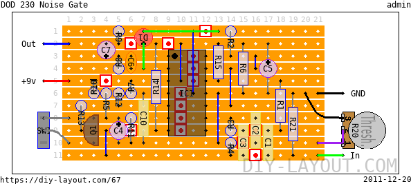
I'm a little bit confused how to hook up the VTL5C10 or the LED/LDR combination.
The VTL5C10 has 4 legs and I can't really see where they might go on the vero?
Is that what the green lines are about?
If I were to make my own LED/LDR combination, how would that be hooked up?
Thanks for helping out
I'm building the DOD 230 from this vero: http://diy-layout.com/67
I'm a little bit confused how to hook up the VTL5C10 or the LED/LDR combination.
The VTL5C10 has 4 legs and I can't really see where they might go on the vero?
Is that what the green lines are about?
If I were to make my own LED/LDR combination, how would that be hooked up?
Thanks for helping out


