Friedman BE-OD Pedal  [traced]

General documentation, gut shot, schematic links, ongoing circuit tracing, deep thoughts ... all about boutique stompboxes.
User avatar
roseblood11
Tube Twister
Information
Posts: 1887
Joined: 23 Aug 2008, 14:21
Has thanked: 366 times
Been thanked: 314 times

Post by roseblood11 »

bancika wrote:it will also be interesting to check out different op-amps. TL072 is so vanilla :) People get obsessed with opamps in tubescreamers.
I have a few different dual opamp types leftover from experimenting with Timmy circuit, I'll give them a try here.

Cheers
Might be interesting. It's a bit strange that the original pedal seems to have oscillation problems at certain settings. Maybe at least the clipping stages were designed around opamps with lower bandwidth? And then the manufacturer chose tl072 for all positions to simplify the production?

Other questions:

Is it worth adding a voltage doubler?

And has anybody built this pedal who also owns a ROG Azabache? I think about putting both circuits in the same enclosure, but I'd like to hear some opinions first. Do they sound good combined? Which order would you prefer? ...

User avatar
rmroza
Breadboard Brother
Information
Posts: 121
Joined: 27 Apr 2010, 13:48
Has thanked: 5 times
Been thanked: 45 times

Post by rmroza »

Well, pedal components populated, but too many chores and hot water heater is on the fritz, so have to wait until tomorrow to wire up and try out.

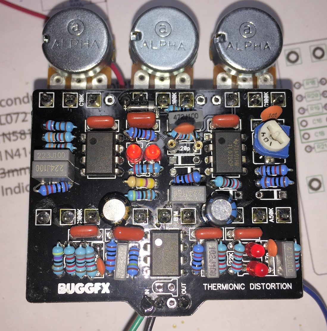
I added socket pins in all diode positions so I can swap out and try different things. I'll have to wire the BJT's up

https://drive.google.com/file/d/0B8xH7Y ... sp=sharing

User avatar
alltrax
Breadboard Brother
Information
Posts: 65
Joined: 28 Mar 2013, 08:29
Location: Bordeaux, France
Has thanked: 20 times
Been thanked: 20 times
Contact:

Post by alltrax »

Bajaman, would you mind posting a pic of your populated board with these ZTX951 (if you have time, don't want to bother you) ?
I'm a bit confused. From what I understand you have a pair piggy backed on C12 as shown page 17, what about the other pair ?
Thanks

User avatar
bajaman
Old Solderhand
Information
Posts: 4549
Joined: 26 Jun 2007, 21:18
Location: New Brighton, Christchurch, NZ
Has thanked: 596 times
Been thanked: 2061 times

Post by bajaman »

what about the other pair ?
There is NO OTHER PAIR :wink:
Just DO NOT fit the four diodes - leave them out - COMPLETELY :!:

ALSO: You must use the ZTX951 devices if you want to get the same response - critical :wink:
be kind to all animals - especially human beings

User avatar
bajaman
Old Solderhand
Information
Posts: 4549
Joined: 26 Jun 2007, 21:18
Location: New Brighton, Christchurch, NZ
Has thanked: 596 times
Been thanked: 2061 times

Post by bajaman »

From what I understand you have a pair piggy backed on C12 as shown page 17
CORRECT :thumbsup
be kind to all animals - especially human beings

User avatar
alltrax
Breadboard Brother
Information
Posts: 65
Joined: 28 Mar 2013, 08:29
Location: Bordeaux, France
Has thanked: 20 times
Been thanked: 20 times
Contact:

Post by alltrax »

Ok I get it, thanks :thumbsup

User avatar
J0K3RX
Degoop Doctor
Information
Posts: 1058
Joined: 29 Jun 2011, 01:25
Location: US Florida
Has thanked: 316 times
Been thanked: 556 times

Post by J0K3RX »

Anybody ever gonna post any audio clips? If one of the guys that has the retail pedal could do a side by side comparison that would be great but, I would settle for any damn thing at this point!

User avatar
alltrax
Breadboard Brother
Information
Posts: 65
Joined: 28 Mar 2013, 08:29
Location: Bordeaux, France
Has thanked: 20 times
Been thanked: 20 times
Contact:

Post by alltrax »

I could try to record something basic with my clone if you are interested (from Alex's layout at tagboard)

User avatar
Matt310
Information
Posts: 2
Joined: 23 Jun 2017, 11:48

Post by Matt310 »

Issue resolved... TL072 put backwards... stupid issue ! Don't build effects pedals when you are tired!

User avatar
rmroza
Breadboard Brother
Information
Posts: 121
Joined: 27 Apr 2010, 13:48
Has thanked: 5 times
Been thanked: 45 times

Post by rmroza »

"Anybody ever gonna post any audio clips? If one of the guys that has the retail pedal could do a side by side comparison that would be great but, I would settle for any damn thing at this point!"

No shit. I WILL, but first I need to get a working pedal. As some of these guys have the original and working pedals, I thought they'd be the first to post. Likewise, feedback on replacements for BAV99s

"Don't build effects pedals when you are tired!"

...or amps. Sold an amp earlier this week. i mae some MODs to it. The guy contacted me with photo and asked what this was. I replaced the slope resistor and soldered it completely in the wrong spot and off of the plate somewhere!!! :O Too tired.

I will get mine complete and hopefully it will work, but not sure when I will be able to A-B even if it works probably until Sunday! Why?? I'm working them concert tonight. Tomorrow morning need to be up for people coming over to demo amps and off ot a CD release listening party! Busy, busy, busy!

User avatar
rmroza
Breadboard Brother
Information
Posts: 121
Joined: 27 Apr 2010, 13:48
Has thanked: 5 times
Been thanked: 45 times

Post by rmroza »

Uh.

Well, off work and wired all of the pots up. I used a fresh 9V battery for juice.

With the diodes in, the pedal is again noisy and humming and unusable!

I removed all of the diodes and replaced with the PNP resistors. Substantially less noise, but still un-usable! Also, the bass is flubby no matter what settings I used. It may have been with the diodes also so not due to the change, just noted it when the noise less.

I'm not sure what the issue is. All 4 pedals now (2 vero, 1 old PCB and 1 Buggs PCB) all basically used the same components and UNboxed. The only thing I can thing of is boxing it, but I thought people had it unboxed and alledgedly reported it working? I did a video file so you can see and hear for yourself. Sorry nothing to hold the cell phone. If I can get one working, it's probably all the same thing and can get all working, but as of right now, none are usable and so there is no way I can A-B it when I can't even get it working!!!

Video clip - https://drive.google.com/file/d/0B8xH7Y ... sp=sharing

User avatar
bajaman
Old Solderhand
Information
Posts: 4549
Joined: 26 Jun 2007, 21:18
Location: New Brighton, Christchurch, NZ
Has thanked: 596 times
Been thanked: 2061 times

Post by bajaman »

ffs - put it in a metal box :roll: and make sure the circuit ground and pots are connected to the box
be kind to all animals - especially human beings

User avatar
bugg
Breadboard Brother
Information
Posts: 144
Joined: 11 Feb 2013, 03:10
my favorite amplifier: Fender Twin
Has thanked: 51 times
Been thanked: 336 times

Post by bugg »

It sounds like an off-bias or starved fuzz to me.... First I would make sure the Vref supplies are correct to each of the opamps.

Also make sure R30 is 10 ohms, not 10K or something crazy like that.

User avatar
rmroza
Breadboard Brother
Information
Posts: 121
Joined: 27 Apr 2010, 13:48
Has thanked: 5 times
Been thanked: 45 times

Post by rmroza »

Ok. Thanks guys. I'll check things tomorrow. At a jam fest since 7p. It's 1a n still going strong! Good times!

User avatar
alltrax
Breadboard Brother
Information
Posts: 65
Joined: 28 Mar 2013, 08:29
Location: Bordeaux, France
Has thanked: 20 times
Been thanked: 20 times
Contact:

Post by alltrax »

Bugg, I'm populating your pcb and have a question, is the square pad on the trimmer for pin 2 (ie center position) ?
I don't have the same kind of trimmer
Thanks

User avatar
bugg
Breadboard Brother
Information
Posts: 144
Joined: 11 Feb 2013, 03:10
my favorite amplifier: Fender Twin
Has thanked: 51 times
Been thanked: 336 times

Post by bugg »

alltrax wrote:Bugg, I'm populating your pcb and have a question, is the square pad on the trimmer for pin 2 (ie center position) ?
Square pad is pin 1. The other two are connected together.

Image

User avatar
alltrax
Breadboard Brother
Information
Posts: 65
Joined: 28 Mar 2013, 08:29
Location: Bordeaux, France
Has thanked: 20 times
Been thanked: 20 times
Contact:

Post by alltrax »

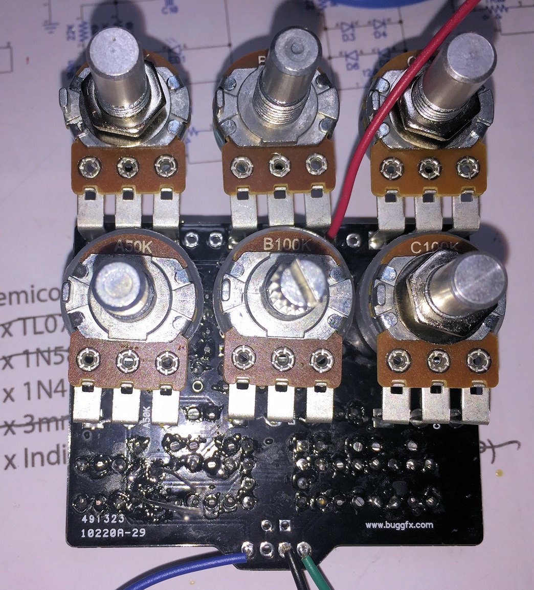
Hi folks I have a problem with my build : no sound. This should be the easiest to fix but I checked all the usual suspects and can't figure it out.
Here are my voltages :
U1 U2 U3
1- 8.6 4.6 4.65
2- 1.35 4.6 4.65
3- 3.1 4.6 3.78
4- 0 0 0
5- 4.3 4.6 4.57
6- 4.6 4.6 4.6
7- 4.6 4.65 4.6
8- 9.25 9.25 9.25

I didn't solder the clippers (1n4148, D3-D6)
Here are 2 crappy pics from my phone :

Image
Image

One thing that puzzles me is the 2 LEDs on the gain pot (bottom right of the board) : I'm sure they are upside down as they should but when I check them with my Peak Atlas devise it indicates both anodes and cathodes on the same side :scratch:

Thanks !

User avatar
Groovenut
Resistor Ronker
Information
Posts: 299
Joined: 07 Jan 2011, 16:31
Has thanked: 60 times
Been thanked: 100 times

Post by Groovenut »

Biggest thing that jumps out is the voltage on pin1 of U1. It should be ~4.5V I would check your paralleled 82k resistors as that is the main path for the bias voltage to get to pin1. If there is 4.5V on pin2 and conductivity on R4 and R5, then you should have 4.5V on pin1.

User avatar
alltrax
Breadboard Brother
Information
Posts: 65
Joined: 28 Mar 2013, 08:29
Location: Bordeaux, France
Has thanked: 20 times
Been thanked: 20 times
Contact:

Post by alltrax »

Groovenut wrote:Biggest thing that jumps out is the voltage on pin1 of U1. It should be ~4.5V I would check your paralleled 82k resistors as that is the main path for the bias voltage to get to pin1. If there is 4.5V on pin2 and conductivity on R4 and R5, then you should have 4.5V on pin1.
I checked R5 which is 41k so that's ok
On R4 pin 1 I have 4,6V ie Vref so that's ok too, R4 pin 2 & R5 pin 1 is 5,9V, should'nt it be the same for U1 pin 2 as the 3 are connected ? So I checked and indeed I don't have continuity on that triple point, while I should according to the schematic.
There is probably a problem around U1 but I guess I still should get some sort of sound on the output, but when engaged on my test box it's dead silent

Thanks for your input :thumbsup

User avatar
rmroza
Breadboard Brother
Information
Posts: 121
Joined: 27 Apr 2010, 13:48
Has thanked: 5 times
Been thanked: 45 times

Post by rmroza »

Well, no time today (Sunday) to check on it either. My furance decided not to work andI spent all day doing yeard work and chopping down and trimming trees, so it'll have to wait until at least tomorrow.

In regard to sqaure pads and LEDs in th above two reponses...yay, that f*cked me up too as the board had sqare in the POSITIVES of the cap and LED, but diodes was the line or negative end!! In any event, I just reverted to the schematic and trace and ensured what direction to place the components. I also found out that yes, on all pots, the square in Pin1!...however and as I said before, some pots are working in the opposite direction! Now easy enough to change by opposite pins, but just noted this throughout the builds and on the Buggs board, some pots still are working in the opposite direction.

Post Reply