Jext Telez - White Pedal [traced]
-
Motter

- Solder Soldier
Great job, and nice tones Frank! You're right, the MRB and cocked wah sounds really make this circuit what it is. Can your circuit run at 9V? I'm not enthusiastic about charge-pumping everything out there the way some builders seem to be.
-
Frank_NH
- Solder Soldier
OK - here's a stripped-down 9V version!Motter wrote:Great job, and nice tones Frank! You're right, the MRB and cocked wah sounds really make this circuit what it is. Can your circuit run at 9V? I'm not enthusiastic about charge-pumping everything out there the way some builders seem to be.
After some LTSpice redesign and a go on the breadboard, it turns out that the gain stages can run comfortably at 9V, but in addition you can simplify the clipping and just make it straight to ground (unlike my 18V version, where I tried to stay truer to the original preamp voltages). I've shown this with some 1N34A clipping diodes but you can retain the original two PNP transistor clipping and experiment with germanium transistors. I think, overall, it retains the spirit of the Conqueror preamp. By the way, the original preamp had a second transistor gain/mixer stage after the tone stack and before going to the power amp, so that could be added if you wanted more output (this gets enough output for a pedal).
Have fun!
- Attachments
-
-
Frank_NH
- Solder Soldier
Thanks again! I'll see if I can get this one built this week. You definitely want to socket the clipping transistors and try out your favorite PNPs. Silicon PNPs will work but perhaps not have the mojo of germanium. I unfortunately don't have very many germanium transistors in my parts stash so I'll to order some from Small Bear.albru80 wrote:Cool! This is the 9V version (with clipping transistors):
-
Frank_NH
- Solder Soldier
Thanks for the offer. Let me get this built first and I'll let you know. The original used the ACY22 PNP germanium transistors, with an hfe minimum of 30. Not sure what the equivalent would be but one could try any of the usual suspects (e.g. AC128...). Also not sure what the effective forward voltage is when wired as a diode, but that would be useful information.Motter wrote:Frank, I've got dozens of germanium transistors and diodes, and I'll never use all of them. Send me your mailing address
https://www.digchip.com/datasheets/part ... 22-pdf.php
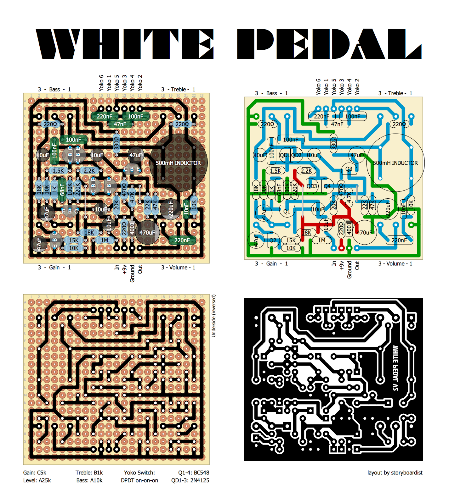
Looking to build this, using the layout by Effects Layouts. I'm a newb with inductors. I've got the Dunlop 500mh inductor for this build. Does orientation matter with inductors? Or can I place the 4 pins any which way?
-
Motter
- Solder Soldier
Well there's two coils in there, so each pair of pins is a separate coil. Measure the dc resistance to find which pairs are connected, and then put them in parallel across the two rails on the PCB.
Edit: oops, the wah inductor should only have one coil. That means you'll only get a measurable DC resistance across two of them. Make sure you have these wired across the rails, the other two are just for mounting and have no electrical connection.
Edit: oops, the wah inductor should only have one coil. That means you'll only get a measurable DC resistance across two of them. Make sure you have these wired across the rails, the other two are just for mounting and have no electrical connection.
Thanks! So if I get a measurable resistance across two leads, then on of those leads will go in the slot connected to the 220ohm resistor and 100nF cap, and the other lead will go in the slot connected to the Yoko 5 switch, 10k resistor and 10nF cap? Sorry to be so dense about this, but again - new to inductors!Motter wrote:Well there's two coils in there, so each pair of pins is a separate coil. Measure the dc resistance to find which pairs are connected, and then put them in parallel across the two rails on the PCB.
Edit: oops, the wah inductor should only have one coil. That means you'll only get a measurable DC resistance across two of them. Make sure you have these wired across the rails, the other two are just for mounting and have no electrical connection.
-
Motter
- Solder Soldier
That is my understanding, yes. The DC resistance may be quite low, so put your multimeter on it's lowest range. The actual measurement doesn't matter, we're just trying to find out which two pins are connected to the coil.

I picked up a very early V1 (#0006), and there's a few small differences for the transistors in my unit:
"45N4AA" instead of BC548 for Q1, which is a PN3565 equivalent.
2SC1849 for Q2.
BC547 instead of BC548 for Q3 and Q4.
These changes should not make any sonic difference.
Q1 [45N4AA] Voltages (+V)
E: 1.45 B: 2.04 C: 3.79
Q2 [BC547C]
E: 0 B: 0.69 C: 0.003
Q3 [BC547C]
E: 2.56 B: 3.24 C: 3.13
Q4 [BC547C]
E: 0 B: 0.73 C: 0.014
Everything else matches.
Video coming soon!
Hi, i got some questions for Frank_NH. Why do you use 4 1n34a instead of two ( does it clips more like germanium transistor does wired as diodes) ? The original circuit use a 1UF cap that bypasses the "diodes" transistors to "ground" . On all the videos i watched of someone using an original conqueror or defiant , the tone dont get darker when they engage the distortion switch.I really try to figure out how it is like that ,may you know why ?
I made my pedal to run at 18 volts so i can get the voltages ratings of the old schematic.I also got a switch for distortion on or off and a switch for MrB on of off with 4 positions (3 originals and 0.0147). I did use the 2 switching transistors also.
I made my pedal to run at 18 volts so i can get the voltages ratings of the old schematic.I also got a switch for distortion on or off and a switch for MrB on of off with 4 positions (3 originals and 0.0147). I did use the 2 switching transistors also.