
...but where is the 5th film cap?
i see in the pics that there are 5 film caps, but this version has 4 only
Basic Audio - Scarab Deluxe [traced]
-
jalmonsalmon

- Solder Soldier
There is a post earlier where John says to remove C8...Intripped wrote:...but where is the 5th film cap?
i see in the pics that there are 5 film caps, but this version has 4 only
I assume that missing cap has something to do with the Tone since I saw it posted on an earlier schematic
-
IvIark

- Tube Twister
Information
Well there's definitely one extra cap and resistor in the gut shots. Maybe the resistor is current limiting for the supply or something?
"If anyone is a 'genius' for putting jacks in such a pedal in the only spot where they could physically fit, then I assume I too am a genius for correctly inserting my legs into my pants this morning." - candletears7 - TGP
-
storyboardist

- Breadboard Brother
Information
My guess is that the tone control is probably more like the Hot Silicon/Mictester Tonebender. If ~arph's guesses on the comoponent values from the first page are right, the 8n2 cap is very close to the other tone control components...
This would be my guess:
This would be my guess:
- Attachments
-
-
storyboardist
- Breadboard Brother
Information
Found out I made a mistake on my perf layout (thanks to deadmenonly for the heads up and partial verify of the layout), so disregard the layout on page 2. Here's the updated one:
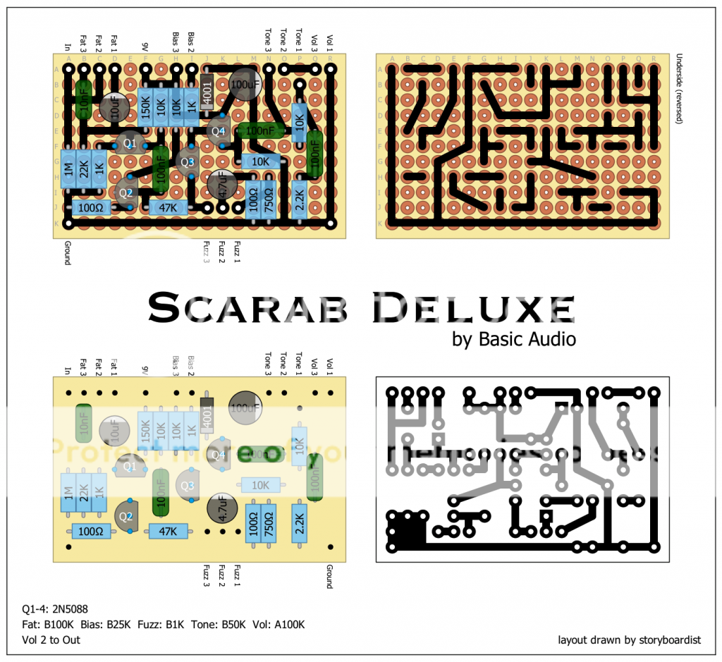
I made another layout reflecting the last schematic I posted with the extra tone control components:

(Just added another row on the right side for the extra resistor and cap)
I made another layout reflecting the last schematic I posted with the extra tone control components:
(Just added another row on the right side for the extra resistor and cap)
-
~arph

- Cap Cooler
This one i guess, it also makes more sense. The dubious 10k parallel with the 50k pot is gone too. I guess we just have to build one and find out if it's close.storyboardist wrote:My guess is that the tone control is probably more like the Hot Silicon/Mictester Tonebender. If ~arph's guesses on the comoponent values from the first page are right, the 8n2 cap is very close to the other tone control components...
This would be my guess:
In the quiet words of the virgin Mary: "Come again?"
-
IvIark
- Tube Twister
Information
Someone verified it with my layout and said it sounds excellent. But it could be excellent and wrong of course.
"If anyone is a 'genius' for putting jacks in such a pedal in the only spot where they could physically fit, then I assume I too am a genius for correctly inserting my legs into my pants this morning." - candletears7 - TGP
-
jalmonsalmon
- Solder Soldier
I made one with your layout Mark and it sounds excellent indeedIvIark wrote:Someone verified it with my layout and said it sounds excellent. But it could be excellent and wrong of course.
- Attachments
-
-
roseblood11
- Tube Twister
Sure, but we still don't know, what's correct. There's definitely a fifth capacitor...jalmonsalmon wrote:I made one with your layout Mark and it sounds excellent indeed
-
roseblood11
- Tube Twister
What we still don't know is, if John selects the transistors for a certain hfe...
-----------------
As I want to try both variations of the tone control, I added a switch to IvIarks layout:

-----------------
As I want to try both variations of the tone control, I added a switch to IvIarks layout:
-
jalmonsalmon
- Solder Soldier
Sweetness... I need to order up some 2N5088s, imo I would select the lowest gain transistors out of a nice batch, and maybe try out some others with higher gains. I will try out this layout in a few days.roseblood11 wrote:What we still don't know is, if John selects the transistors for a certain hfe...
-----------------
As I want to try both variations of the tone control, I added a switch to IvIarks layout:
[ Image ]
Thanks for the added tone control on this layout!
-
HEAD

- Resistor Ronker
Any high gain tranny will do it. I prefer BC550 though... very low noise. Some 47pF caps across the collector-emittor-path of Q2 and Q3 will let it sound even smoother! A James tone controll fits also very nice. A did a build with mictester powser supply filter instead of the 47µF cap and an additional bjt output buffer after the volume pot. Near perfect to my ears!roseblood11 wrote:What we still don't know is, if John selects the transistors for a certain hfe...
- Attachments
-
-
-
roseblood11
- Tube Twister
Nice one, Helge!
Looks like the bigger brother of a "hot silicon" you posted a few years ago, if I remember that right?!
- the extra smoothing cap connects collector and base ... I hope
- the trimmer is the collector resistor for Q3?
- you are talking about this power conditioner? viewtopic.php?t=14410&p=164328
What's the voltage drop here? I read that R.G. talked about a much higher drop than you actually measured?
-
HEAD
- Resistor Ronker
Thx! I build several versions of this basic circuit. Nearly every peer guitarist plays now one build by me.roseblood11 wrote:Nice one, Helge!
Looks like the bigger brother of a "hot silicon" you posted a few years ago, if I remember that right?!
- the extra smoothing cap connects collector and base ... I hope
- the trimmer is the collector resistor for Q3?
- you are talking about this power conditioner? viewtopic.php?t=14410&p=164328
What's the voltage drop here? I read that R.G. talked about a much higher drop than you actually measured?
To answer your questions:
- Yes.
- No. In this case it's a 100k trim pot replacing the 47k feedback-r between q2 and q3. Gives you a better control over the max available gain and compression.
- Yes. For the voltage drop I didn't care because it had no audible effect to my ears. But as far as I remember it was ~0.4V since I always use a 1N5817 schottky diode.
-
kinski
- Resistor Ronker
Hey roseblood11, did you ever build your vero with the tone switch? If so, can you hear much of a difference between the two? Any thoughts?roseblood11 wrote:What we still don't know is, if John selects the transistors for a certain hfe...
-----------------
As I want to try both variations of the tone control, I added a switch to IvIarks layout:
[ Image ]
-
Cub

- Cap Cooler
Found this on the blog of drdFX Stompboxes. A nice post and a link to a project PDF with a PCB layout for a 1590A ! There's also one for 125B enclosures, though the contributors to this thread already got you covered for that.
http://drdfx.hu/en/ankh/
http://drdfx.hu/en/ankh/
I wish I were a chestnut tree, nourished by the sun.
With twigs and leaves and branches and conkers by the ton.
With twigs and leaves and branches and conkers by the ton.