E.W.S Tri-Logic II Bass Preamp [traced]
- chicago_mike
- Tube Twister
It's been RE'd.
Its a really simple clean design. 3 band preamp with an input gain control.
I might buy the pedal one more time to do a full on RE...but I think its already solved..perhaps.
I will get the robotalk II pedal in a couple weeks and put that up though.
Its a really simple clean design. 3 band preamp with an input gain control.
I might buy the pedal one more time to do a full on RE...but I think its already solved..perhaps.
I will get the robotalk II pedal in a couple weeks and put that up though.
Skyline FX 2013
- OrionManMatt
- Breadboard Brother
chicago_mike wrote:It's been RE'd.
Its a really simple clean design. 3 band preamp with an input gain control.
I might buy the pedal one more time to do a full on RE...but I think its already solved..perhaps.
I will get the robotalk II pedal in a couple weeks and put that up though.
I still have mine, if you're interested.
Also, in the mean time, what can I do to help? I've been out of pocket here for awhile, unfortunately.
- chicago_mike
- Tube Twister
I think just double checking the off-board wiring.
Skyline FX 2013
- OrionManMatt
- Breadboard Brother
I double-checked what I originally wrote on page three. Here is the revised list. Since I am still terrible at drawing schematics, I'll have to write it out again. I'll just try writing it more clearly this time.
Based on the orientation of the trace side picture (page three):
top right four:
white goes to post 1 on the volume pot;
blue, post 3, mids pot;
green, post E, mids switch; and
yellow, post 1, mids pot;
top left seven:
grey to ground;
group one of blue, green, and yellow to posts 3, 2, and 1, respectively, on the bass pot; and
group two of blue, green, and yellow to posts 3, 2, and 1, respectively, on the treble pot;
middle left two:
grey, post 2, gain pot;
white, post 3, gain pot;
bottom left two:
white, post A, passive/active switch;
red to DC; and
bottom right one:
red to LED.
Bypass Switch wiring:
1: white to post 2, volume pot;
2: white to output;
3: white to input; connected to six;
4: connected to nine;
5: white to post A of P/A switch;
6: connected to three;
7: grey to LED;
8: grey to ground; and
9: connected to four and eight.
Mids switch (assuming left side is A, B, and C, and right is D, E, and F):
A, D: 473k
B: to post 2 on the mids pot
C, F: 154k
E: board (mids group at top right)
Passive/Active switch (assuming left side is A, B, and C, and right is D, E, and F):
A: to board and bypass switch
B, E, and F: 100k R
C: to ground
D: empty
Grounds:
post 3 of volume pot;
post C of P/A switch; and
post 8 of bypass switch.
Input grey to DC
Potentiometers:
Volume: B5K
Gain: B250K
Bass, Middle, and Treble: B50K
IEarlier in the thread the gain pot was determined to be 200k with 24k in series and the volume as 250k rather than 5k....perhaps we are dealing with different versions of this pedal?
Any insight into the mosfet at the begining? I don't understand why they didn't just skip it and have input straight into the IC...
- OrionManMatt
- Breadboard Brother
I think he was using those numbers from memory. The values I listed were taken directly from the pots.bufferz wrote:IEarlier in the thread the gain pot was determined to be 200k with 24k in series and the volume as 250k rather than 5k....perhaps we are dealing with different versions of this pedal?
Any insight into the mosfet at the begining? I don't understand why they didn't just skip it and have input straight into the IC...
BS170. But other than that ... I'm not really sure. What do you mean?
- OrionManMatt
- Breadboard Brother
Yeah, I wish I knew enough to answer your question.
Maybe someone else can help us with that? And with the other stuff.
- chicago_mike
- Tube Twister
This circuit is the same as that inside the Xotic basses...so in that case I bet the Fet is just a simple buffer stage.
Skyline FX 2013
- alexradium
- Resistor Ronker
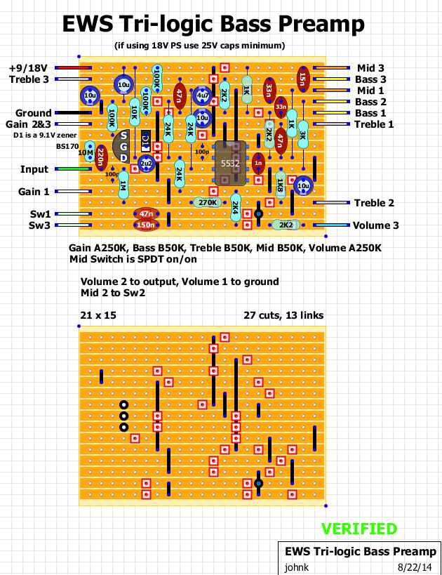
the original has 10K resistors on drain and source of the mosfet,if you put 100k it attenuates the signal.johnk wrote:I just built one today and it works as it should and sounds great.
I used the schematic posted earlier in this thread to make this vero for it.
[ Image ]
Thank you a lot for the vero version! I'll try to build it!johnk wrote:thanks. I installed the 10K and it's A LOT better now.
The only correction to do in the vero layout you posted is the replacement of the 100k resistor (the one linked to bs170 source) with a 10k one?
- smackoj
- Breadboard Brother
Is anyone here making the PCB for this bass pre? If so, I'm interested in one ready to populate. I know a lot of you use the verobrd layouts but I tend to mess those up and do a lot of work por nada......gracias
- batteryacidtea
- Breadboard Brother
John K, I built the Trilogic II using you layout, and I'm getting an horrid background noise that I just can't get rid of. Any ideas of what could be causing this? I've been debugging it for a few days now and it's driving me nuts!
- batteryacidtea
- Breadboard Brother
Thanks for the reply! It's really awkward, and I'm not a begginer, i've been building pedals for some years now, and already checked for cold solder joints, changed the IC, mosfet, redid the wiring, changed the capacitors, triple checked the component values. Dang, sometimes I just hate making pedals hahaha. Do you know any other bass preamp with 3 band eq, level and gain? And thanks again man!
johnk wrote:I just built one today and it works as it should and sounds great.
I used the schematic posted earlier in this thread to make this vero for it.
[ Image ]
Would anyone be so kind as to create a "PCB" assembly layout for this veroboard? Thank you!
Hello! Taht 24k resistor on NE5532 Pin 3 should be a 47k according to my original Trilogic PCB that i have here!johnk wrote:I just built one today and it works as it should and sounds great.
I used the schematic posted earlier in this thread to make this vero for it.
[ Image ]
- george giblet
- Resistor Ronker
I've updated the schematic based on the thread info; see attached pic.
I forgot to add I did re-trace this and identify all parts from the pics that were visible.
Here's a rough summary of the thread.
Chicago Mike and OrionManMatt
both posted pics but they seem slightly
different. Chicago Mikes has 1k8 on the treble
and OrionManMatt has 1k0. The gain pot
wire colors are also different.
p1 Chicago Mike said mids were 15n and 47n.
(The 15n is fixed. The 47n is switched and
the other switched cap is unspecified)
p3 OrionManMatt matt confirms electros
and say mid caps are 47n and 150n
Also says passive switch uses 100k.
p6 Chicago Mike speculates Vol pot at 250k (but maybe not)
p6 Nikifena says: (from Xotic bass)
10M MOSFET,
Gain is 24k + 200k trimpot,
*** Mids 47n and 100n; no 2.4k.
p7 alexradium, 270k across Vol pot
removing 2.4k shifts mids too far
p9 OrionManMatt, Outlines his trace:
BMT 50kB, Gain 250KB, Vol 5KB
Mid caps: 47n and 150n; (through two contacts)
Active/Passive 100k resistor ; (parallel with input; through 2 contacts)
alexradium, say source resistor is 10k
p9 Halfeld, 24k resistor on NE5532 Pin 3 should be a 47k
[It can easily be seen to be 24k on the photos. So this is a variant.]