I notice the Experience uses 1n4001 silicon diodes and all 100k pots instead of germanium diodes and 50k pots. From my memory the Experience had a lot more fuzz and sustain to it than any Foxx Tone Machines I've played through. I'll have to try it out.
Unless I'm missing the question due to gin intake, it is indeed used in series after your effect of choice. The previous clips of scrambler/fuzz factory illustrate this. I've been curious about the stacking and how it works well with over-the-top fuzzes but not some others. I've yet to breadboard it and get around to doing some firsthand things because the addiction pulls me in all sorts of directions and summer has made it too hot to move in any, but I'd suggest breadboarding it and sticking it after your fuzz of choice. Someday I'll do this as well. Someday.
Folks, I find several discrepancies in the schematics depicted here
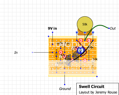
Jeremy, the breadboard version you show here is not coincident with neither the original Anthony Leo circuit, nor with the Experience Pedal swell circuit (assumed this is correct...).
The 50k pot on the original connects between the emitters. The Exp. Pedal swell pot connects from the emitter of Q1 to the 680k resistor. Your version has the 50k pot between emitter of Q1 to base of Q2 according to the drawing.
Can you shed a little more light on this?
As I suspected, the circuit is not a stand-alone device. In the P.E. Experience Pedal it is an integral part of another device and they cleverly made it to steal away the bias of subsequent active components. This is akin to a tube-amp bias tremolo, except it is triggered by the signal itself.
Being a very basic circuit, it only works within limits as some folks noticed.
This circuit would need a wrapper around it to make it more reliable and versatile.
I listened to a youtube demo of the P.E. Exp Pedal and towards the end they demonstrate the swell sound. As I said, lousy as a swell, great for psychedelic effects. But you folks might instantly know of a better solution anyway .
aquataur wrote:
The 50k pot on the original connects between the emitters. The Exp. Pedal swell pot connects from the emitter of Q1 to the 680k resistor. Your version has the 50k pot between emitter of Q1 to base of Q2 according to the drawing.
Q1's collector is connected to Q2's base, so you could say the pot is connected to Q1's collector. This wouldn't be far from the Experience, with a tiny 470ohms between collector and pot. IMO, the effect was pretty noticible and interesting on the demo video, its a wonder there isn't more interest in this little circuit.
No, not all two-transistor circuits are fuzz face descendants
Thanks for the redraw.
This makes it even more obvious that the circuit won´t work with all devices after it.
I personally think the swell effect, although present, is lousy compared to (agreed more elaborate) other implementations.
But in extreme settings it seems to make the sound that the beforementioned guy was allegedly able to achieve.
I hesitated to sling one together because I suspect that it won´t work with any of the gear I have just as-is without further investigation.
I wonder if any of you guys who have the P.S. device or even the working excerpt to confirm this action.
aquataur wrote:In the P.E. Experience Pedal it is an integral part of another device and they cleverly made it to steal away the bias of subsequent active components
Are you saying that it's not used in series in the Experience? I'm confused by what you're referring to with respect to the bias of subsequent active components. From the experience layout it is just in series after the effect, but only when the octave is switched on. Unless I'm missing something obvious.
The drawing of rousejeremy that shows the (complicated) switching is not quite clear to me. The switch symbols he uses are uncommon for me, so it is hard for me to interpret what is really going on.
It looks like the swell circuit is interacting with the other circuit.
What supports this thesis is the fact, that some people observed that the swell unit is not working with all successors.
It is standard engineering practise these days that all audio circuits are to be free of dc on their outputs.
So, as a precaution, all inputs and outputs are either coupled via a capacitor of suitable size or other measures are taken to maintain dc free coupling.
Virtually all inputs (except most traditional valve amp inputs) are capacitor coupled.
I do not see how a unit´s functioning can rely on the fact, that the successor´s input is not dc-isolated via capacitor.
And if they did, that would be a lousy implementation. But you never know...
Sometimes it is hard to tell from a distance, with several people´s inputs inbetween...
Here's a picture of the component side with the wiring. The second one
is not my pedal though one can make out the leads more clearly. Compare this wiring
to the artwork I posted to verify it matches what's found in the PE Exp. box.
I'll need to extricate all the parts from mine to reveal the board and get yez a tracing view.
Cheers,
Kinda... aquarius + taurus.
An astrologer once said to me, this combination is akin to an astronaut ready for the launch, but all he has is a tractor. So I sit in full space suit on my tractor (mind: this is hot-rodded at least ) and plough the field
noelgrassy wrote:
Check yer PM.
Done. Thanks for your time.
Since the original PCB artwork of that PCB seems lost and since this board does not seem verified I doubt wheter one should invest more time in it. For a second I considered making a new board but this appears futile in the presence of verified boards for the foxxtone. There are at least two of them around. It seems rather intelligent to make a little PCB for the swell circuit and that I will do. As soon as this is ready I will put it up here.
(Cannot modify my previous post so here is a new one...)
Noel, you could do us a sublime favour. I just noticed that the schematics that are around all have different pot values for the foxxtone part (and even the swell...).
Please have a look at the pot values and laws and let us know, thanks