Page 2 of 5
Re: Emerson Custom Guitars E-M Drive.
Posted: 14 Oct 2012, 18:39
by FiveseveN
harmaes wrote:But I'd love to hear your opinions about them.
Well they couldn't very well brag about a grounded-emitter amplifier, could they? Gotta have them NOS PIO OMGWTFBBQ!
Re: Emerson Custom Guitars E-M Drive.
Posted: 14 Oct 2012, 19:07
by harmaes
Hehehe

Re: Emerson Custom Guitars E-M Drive.
Posted: 15 Oct 2012, 01:04
by caspercody
I am testing this through a all tube amp.
Re: Emerson Custom Guitars E-M Drive.
Posted: 27 Jan 2013, 17:44
by SDB Guitars
I can't read the pot values... anyone know what they are?
Re: Emerson Custom Guitars E-M Drive.
Posted: 27 Jan 2013, 22:03
by IvIark
I think this right. Someone already built it on my blog and said it's a nice boost
Mojo version if you've got the Russian caps:
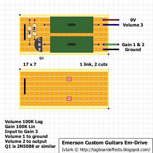
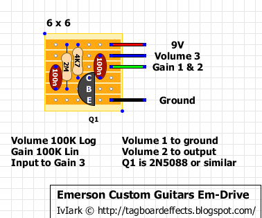
Compact version:
Re: Emerson Custom Guitars E-M Drive.
Posted: 28 Jan 2013, 03:19
by SDB Guitars
Thanks, IvIark! Just threw this together, and I like it! Just used Mylar caps, as I didn't have any "old school paper in oil" on hand, but still, it sounds decent. Also, it's a confidence booster, as I slaved over tagboard versions of the Deep Blue Delay and Eternity pedals with absolutely no success. Maybe I just needed something EXTREMELY simple and straightforward to ease me into pedal building.

Re: Emerson Custom Guitars E-M Drive.
Posted: 30 Jan 2013, 23:19
by IvIark
That's a pretty good idea. Once your confidence is up then you'll knock anything out comfortably I'm sure
Re: Emerson Custom Guitars E-M Drive.
Posted: 31 Jan 2013, 16:37
by nooneknows
Nocentelli wrote:Maybe, but I'm inclined to think this is mainly aimed at driving the input of a nice tube amp rather than primarily producing the clipping from within the transistor itself.
+1
I breadboarded it and it doesn't sound interesting itself, but if I use it to drive my amp or even my OCD input then it sings really well. Anyway I still prefer my electra distortion derived woodrow clone to do this.
Re: Emerson Custom Guitars E-M Drive.
Posted: 31 Jan 2013, 16:41
by caspercody
If you used the schematic on page 1 from IvIark I think it is wrong. R1 (I think) should be going to V+ and not to R2 and C2??
Re: Emerson Custom Guitars E-M Drive.
Posted: 31 Jan 2013, 16:45
by IvIark
Yes that was the mistake in my guessed scheme. This is the correct one apparently
http://www.extremecircuits.net/2010/05/ ... istor.html
Edited:
I've updated my schematic to add it to the thread.
Re: Emerson Custom Guitars E-M Drive.
Posted: 01 Feb 2013, 06:10
by SDB Guitars
IvIark -
Are you going to update the vero layout on your blog to match the new schematic? (I have not checked to see if you have or not, juts curious).
Re: Emerson Custom Guitars E-M Drive.
Posted: 01 Feb 2013, 06:53
by tyronethebig
looks like both resistors go to V+ on the vero
Re: Emerson Custom Guitars E-M Drive.
Posted: 01 Feb 2013, 09:38
by IvIark
Yes the vero is correct, it was my original gues-timate scheme from October that was wrong
Re: Emerson Custom Guitars E-M Drive.
Posted: 06 Feb 2013, 19:10
by rugeb
Originally, what transistor they use: 2N50088 or Darlington?
Re: Emerson Custom Guitars E-M Drive.
Posted: 07 Feb 2013, 03:40
by sonicmojo
nooneknows wrote:Nocentelli wrote:Maybe, but I'm inclined to think this is mainly aimed at driving the input of a nice tube amp rather than primarily producing the clipping from within the transistor itself.
+1
I breadboarded it and it doesn't sound interesting itself, but if I use it to drive my amp or even my OCD input then it sings really well. Anyway I still prefer my electra distortion derived woodrow clone to do this.
+2 on the breadboard results here but it might be a interesting in the chain of a bigger circuit.
Re: Emerson Custom Guitars E-M Drive.
Posted: 07 Feb 2013, 10:44
by rugeb
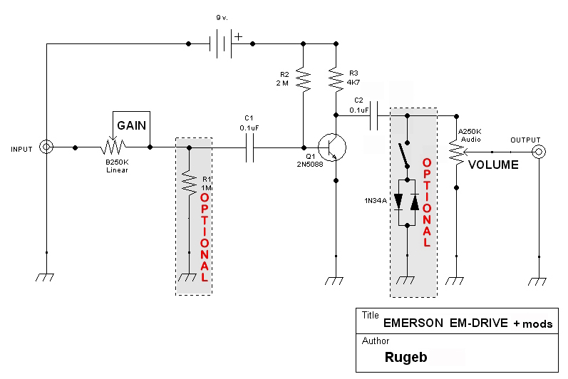
Schematic with mods: Pulldown resistor (anti-pop) and clipping diodes (for transistor amps):
Re: Emerson Custom Guitars E-M Drive.
Posted: 07 Feb 2013, 13:23
by nooneknows
sonicmojo wrote:
+2 on the breadboard results here but it might be a interesting in the chain of a bigger circuit.
Uh, I didn't understand.
I tried it (in breadboard version) alone in front of my tube peavey amp, after my pedalboard setup (lovepedal woodrow, digitech main squeeze compressor > crybay wah > Phase 45 > OCD > MiniBooster > digitch chorus factory > hardwire delay > Boss Tuner) and before my pedalboard, the best results were using it
before the pedalboard, driving the OCD engaged.
Re: Emerson Custom Guitars E-M Drive.
Posted: 07 Feb 2013, 13:37
by nooneknows
Anyway this circuit seems to be drawn having in mind the audiophile rules: minimum number of components, hi-quality caps, ecc.
Since I was in audiophile tunnel and addiction for some years and it took a long time before I finally came out, let me say that I think a great part of the mojo around is... crap.
If in hi fi world it 'could' work (but not always) in guitar land is almost useless: guitar is definetely not hi-fi, and much more 'often' than 'sometimes', audiophile rules become a synonime of 'shrillness' or stiff sound.
But that's just my humble opinion.
Re: Emerson Custom Guitars E-M Drive.
Posted: 08 Feb 2013, 03:59
by aaronmcoleman
I've breadboarded this, because why not...I had an extra 3 minutes today. I tried 2n5088s, 2n5089, 2n2222, 2n3094, and 2n3096. The lower gain options sounded better but boring. The higher gain options just got farty and blown out with the gain cranked. That's always been my experience with single transistor circuits. So, what's the secret, how does this not get "farty"?
Re: Emerson Custom Guitars E-M Drive.
Posted: 08 Feb 2013, 07:27
by sonicmojo
aaronmcoleman wrote:I've breadboarded this, because why not...I had an extra 3 minutes today. I tried 2n5088s, 2n5089, 2n2222, 2n3094, and 2n3096. The lower gain options sounded better but boring. The higher gain options just got farty and blown out with the gain cranked. That's always been my experience with single transistor circuits. So, what's the secret, how does this not get "farty"?
For a circuit this minimalistic, I think you can only get so far, especially with cranked turns of the gain pot. I've had better luck with single transistor circuits like the COT50 which is very similar but puts something between emitter and ground which I think makes things more more controllable.