It has been my experience that the FF will work with a range of transistors, however there is a sweet spot in the gain ranges for Q2&3 which gives you the best range of oscillation and gated sounds. Surprise surprise, it's between 70 and 120hfe.
I have used 2N3906's successfully, and they sound great but slightly more compressed.
The ones i've tried worked up to ~240hfe, but didn't sound quite right.
Interesting to note, this circuit seems to like leaky Ge transistors, which seems to help it to oscillate, though I can't see why.
Zvex - Fuzz Factory [traced]
Information
- Posts: 7
- Joined: 02 Nov 2011, 03:36
Hi,
I was wondering if someone can throw me a bone here.
I built this and it don't quite sound right.
Sounds clippy and cannot adjust to oscillation.
My question is this since there are schematics and vero board layouts and 46 pages of dialog on this project and Q1 Q2 and Q3 referenced throughout and I have a B&K Transistor tester and noticed my Ge transistors AC128K have gains of 150 and 200 where should I put the Higher hFe transistor towards the output jack or more towards the center between the Si and the other Ge?
Or, should I continue to sort through more AC128Ks to find something with lower gain?
Goodness, this thread has become obfuscated over the years.
Thanks
Dave
Information
- Posts: 7
- Joined: 02 Nov 2011, 03:36
I think I found the problem, and it has to do with the hFE of one of the transistors. more to follow.

Information
- Posts: 7
- Joined: 02 Nov 2011, 03:36
Definitly found the problem, and it has to do with the hFE of one of the transistors.
So I bought these transistors to build a FUZZ FACE because the Ge transistors I bought at the MIT Flea market for 3 bucks did not work in the FUZZ FACE circuit.
25 matched pairs of AC128K/AC176K.
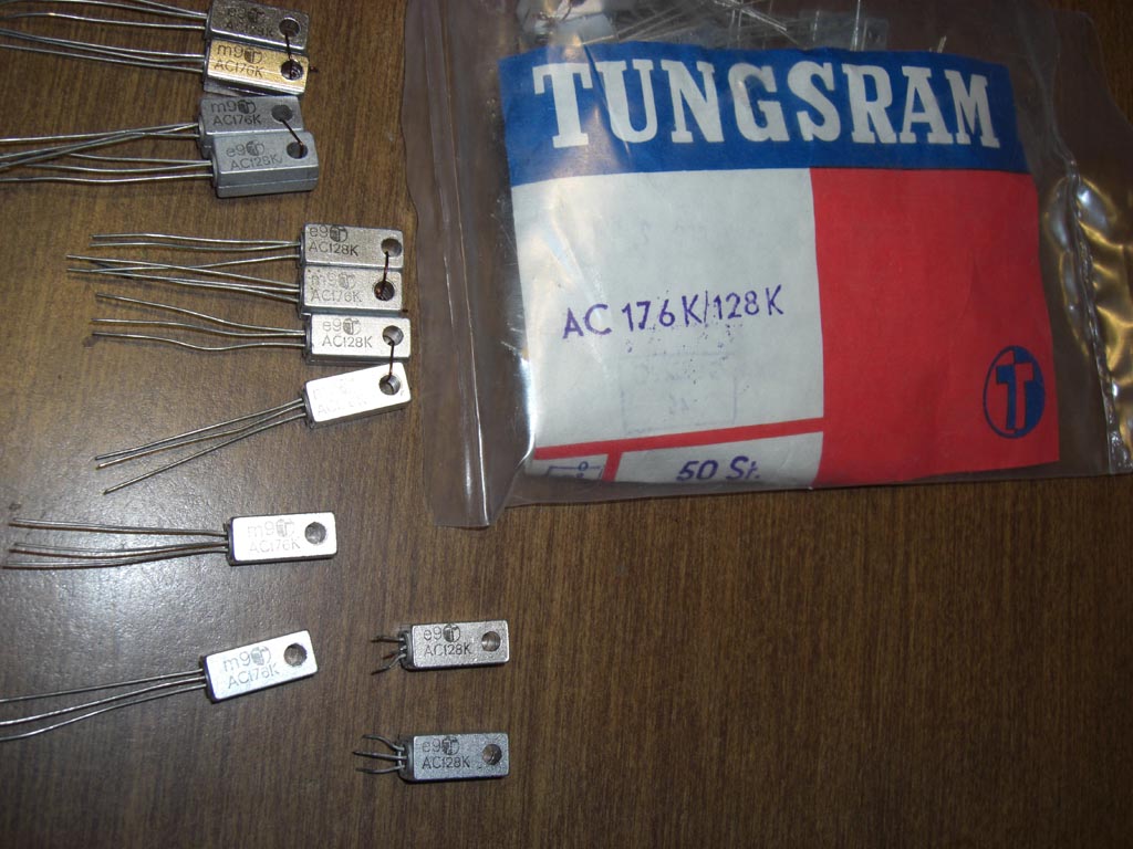
So I check the hFE of the AC128Ks I put in the FUZZ FACTORY one was 115 the other was around 75
I then checked 4 more of the AC128Ks in the bag and pick 2 that had hFE around 105 and put them in the FUZZ FACTORY and, Voilà! it works.
at this point I start to think... what about those transistors I bought at the MIT Flea?
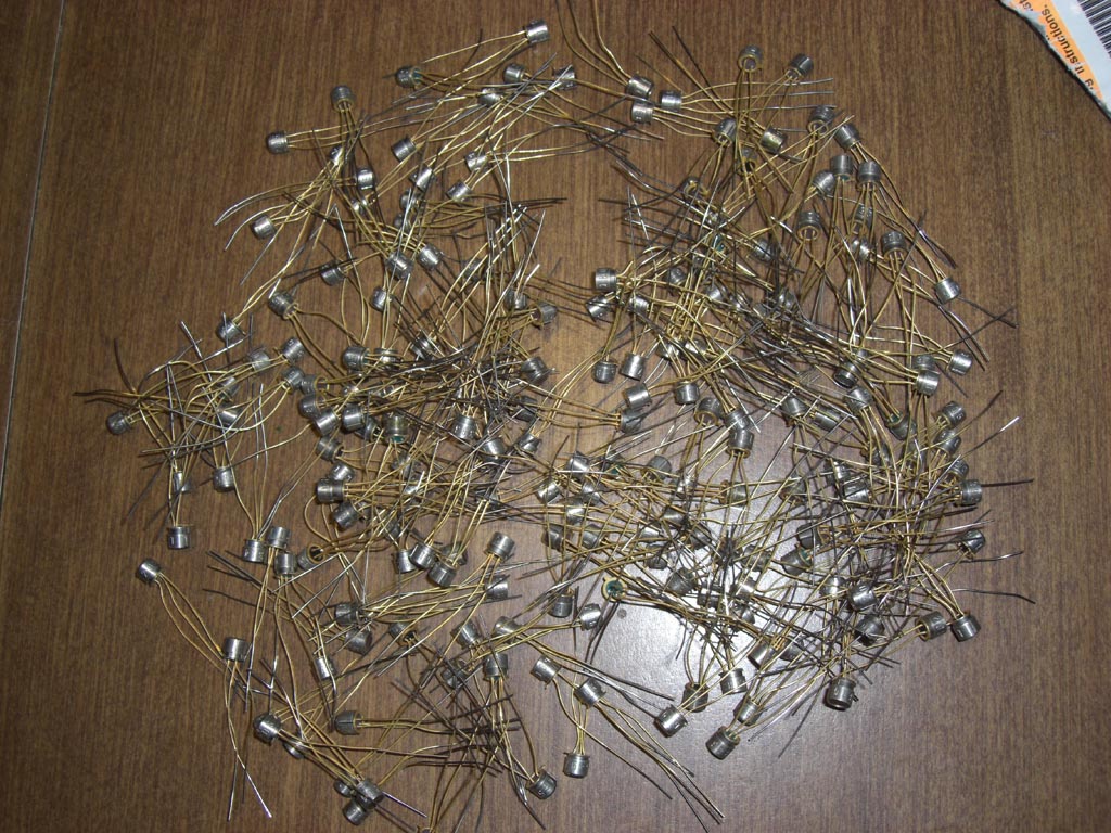
I put 2 of these in the FUZZ FACTORY and it appears to work the same as the matched AC128Ks
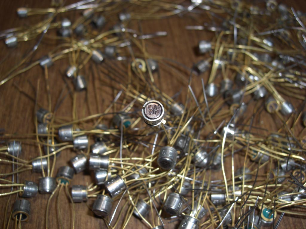
I have no idea what these transistors are. They came from an IBM research facility and each one is banded with a serial number obviously from benchmark testing. They are marked IBM on the top and they test very low leakage PNP Ge
What the heck am I going to do with all these parts?
next is SEEK FUZZ I guess.
So I bought these transistors to build a FUZZ FACE because the Ge transistors I bought at the MIT Flea market for 3 bucks did not work in the FUZZ FACE circuit.
25 matched pairs of AC128K/AC176K.
So I check the hFE of the AC128Ks I put in the FUZZ FACTORY one was 115 the other was around 75
I then checked 4 more of the AC128Ks in the bag and pick 2 that had hFE around 105 and put them in the FUZZ FACTORY and, Voilà! it works.
at this point I start to think... what about those transistors I bought at the MIT Flea?
I put 2 of these in the FUZZ FACTORY and it appears to work the same as the matched AC128Ks
I have no idea what these transistors are. They came from an IBM research facility and each one is banded with a serial number obviously from benchmark testing. They are marked IBM on the top and they test very low leakage PNP Ge
What the heck am I going to do with all these parts?
next is SEEK FUZZ I guess.
-
slim_blues_boy

- Breadboard Brother
Information
- Posts: 103
- Joined: 17 Feb 2009, 12:51
you could send those transistors to meDavy Boy Smith wrote:
What the heck am I going to do with all these parts?
well anyway just curious, have you tested all of your pair Tungsram AC128K/AC176K?
I once bought Tungsram AC128 & AC176, most of them were leaky and, even all AC176 were unusable.
you should try 2N404 for this fuzz factory, works really well for me. clean up very very nicely when you roll down volume pot on your guitar.
-
aegert

- Solder Soldier
Green... I have 1000's like this I think they are 2n1188's what is the leakage on them? if they run with good strong gains many upwards of 140-175hfe with leakage ranging from 15 to 25mA I would bet they are 2n1188's 
I just built this up and I swapped everything from Q2= 70-90 and Q3= 90-140 all 2n404a Ti Gold Grey bottom Jan and the Q2=88 , Q3=135 won....
I am convinced that the stab would be much better served as an audio or 'C' taper. I am going to test this out. As its a Rheostat I have to test out which taper works best...
As for the standard build reading this whole thread was painful LOL I should get thumbs up for sitting through it ROFL but From my read a couple of things came to mind:
1) if you are building with linear pots and pol 2 is wired correctly it doesn't matter if you wire 3 as 1 as a linear is a mirror it will work either way. Granted you need to wire the pots as if 1 was 3 or vice versa. All wire need to follow
2) I don't know but a few comments about Vero boards and scraping breaks in copper for voids/ cuts... I use a small drill bit and just drill from the component side strait through the board. It removes everything and I don't have to match up the grid in reverse. I test with a continuity tester before wiring up to make sure the cuts are good but 99.99% they are great . I just take a marker and mark the wholes to drill and Bang bang bang the board is cut
3) I suck at drilling enclosures ROFL... If anyone has a good drill template for this I would be thumbs upping you big time
Here you go, this is for a 1590 enclosure. I use the small Alpha 9mm pots.aegert wrote: 3) I suck at drilling enclosures ROFL... If anyone has a good drill template for this I would be thumbs upping you big time
https://dl.dropbox.com/u/20272266/Zvex- ... -2-Bat.pdf
I have included the approx size outline of my switches and jacks, this helps with parts placement. A 9v battery should fit snugly in the middle. I use the vertical vero layout with on board pots from sabrotone.com for this - thanks Harald
Information
- Posts: 3
- Joined: 14 May 2012, 06:13
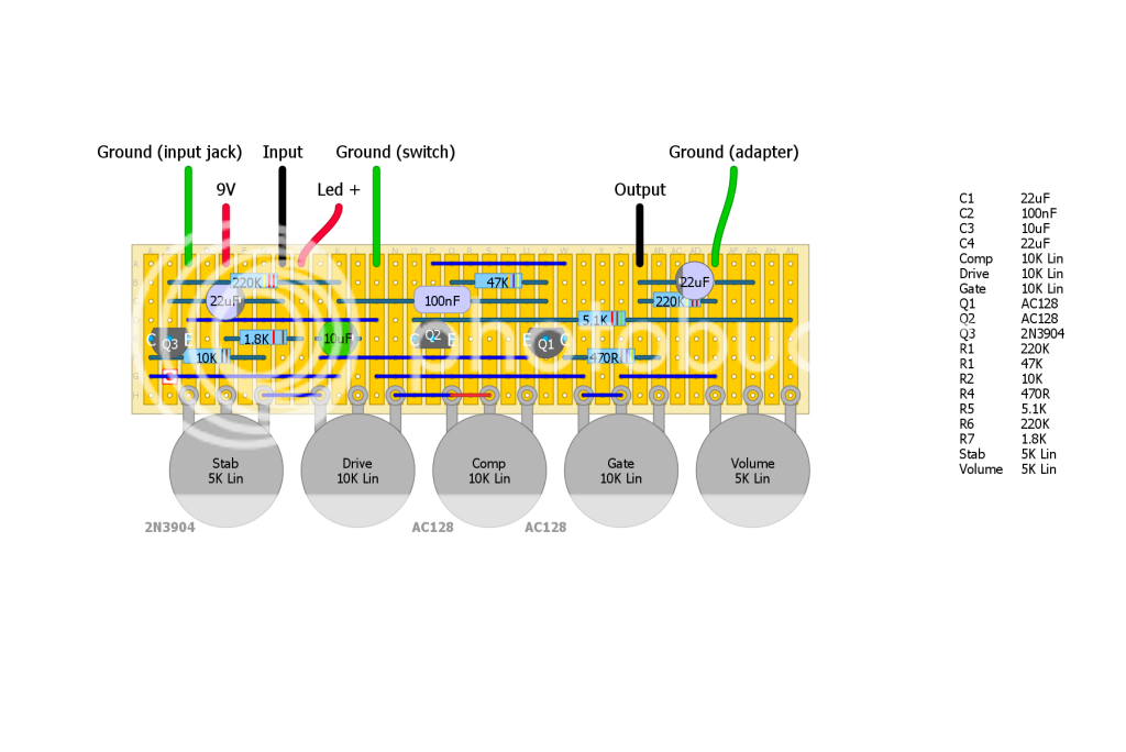
Is this the latest and most accurate layout at the moment (http://www.aronnelson.com/gallery/main. ... s.png.html)???? If not can someone post or PM me a link to it?
-
Renegadrian

- Solder Soldier
Ibanezsr500 wrote:Is this the latest and most accurate layout at the moment (http://www.aronnelson.com/gallery/main. ... s.png.html)???? If not can someone post or PM me a link to it?
I built some using that layout and posted as verified, so go without worries!!!
Information
- Posts: 3
- Joined: 14 May 2012, 06:13
Renegadrian wrote:Ibanezsr500 wrote:Is this the latest and most accurate layout at the moment (http://www.aronnelson.com/gallery/main. ... s.png.html)???? If not can someone post or PM me a link to it?
I built some using that layout and posted as verified, so go without worries!!!
Thanks Mate, very helpful.
hi all,
I'm goin' to build the Fuzz Factory from this layout too, but I can see that if I solder as from the layout when I'll mount all in the box I will have all the controls and plugs mirrored..
I 'll have stab on the left and volume on the right etc..
also the input jack will be on the left of the pedal....weird..
is it intended to be done this way?
L
-
induction
- Resistor Ronker
I think that if you mount the pots with the tabs pointing toward the top (north?, whatever) of the box, everything will line up right.looksharp wrote:hi all,
I'm goin' to build the Fuzz Factory from this layout too, but I can see that if I solder as from the layout when I'll mount all in the box I will have all the controls and plugs mirrored..
I 'll have stab on the left and volume on the right etc..
also the input jack will be on the left of the pedal....weird..
is it intended to be done this way?
L
I liked Harald Sabro's layout with board-mounted pots and components facing south, but I didn't like the reverse-ordered pots, so I revised his layout to reorder them. The 1K8 resistor is for the led. The other layout is smaller, but the mounted pots are convenient. Mine works, but I won't call the layout confirmed unless someone else builds it because I drew it after I built it. Should fit in a 1590B (landscape orientation), but I used a BB so I don't kick the knobs.
thanks for your reply.
mhhhh...Sabro's layout got all the pot in the right order like the original (volume on the left etc)
remember that actually looking at his layout you are seeing the circuit and the pots from its bottom like you see them when you remove the bottom cover of the pedal...just right. When you close the pedal and put it on the floor all the control are fine and at "north" and the pedasl switch south..
in your layout, maybe I'm confused, it seem to me that you'll end up with the controls south or at least in the middle of the enclousure and then the pedal switch at north...correct me if I'm wrong..
L
-
induction
- Resistor Ronker
Well Sabro's layout will give you the correct order if you put the board in the center of the box instead of vertically at the north edge, but that might get in the way of the switch (or might not, I don't know). Look at the photos of the finished pedal on his page, his pots are in reverse order.
My layout probably makes more sense if you look at a gutshot. Here's my build.
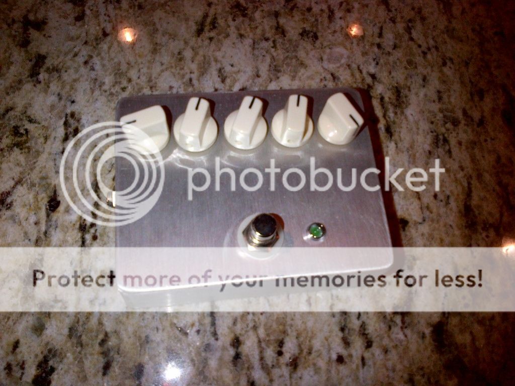
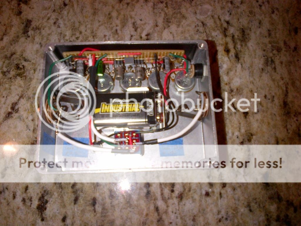
The pots aren't labeled, but take my word for it, volume is on the left.
As for the Factory De Fuzz layout (I assume that's the one you're referring to), print it out and rotate the picture 180 degrees (or just imagine doing so) so that the volume is on the right and the lugs are pointing north. Now since you're looking at it from the back, and volume is on the right, volume will be on the left when you look at it from the front (the side with the knobs).
My layout probably makes more sense if you look at a gutshot. Here's my build.
The pots aren't labeled, but take my word for it, volume is on the left.
As for the Factory De Fuzz layout (I assume that's the one you're referring to), print it out and rotate the picture 180 degrees (or just imagine doing so) so that the volume is on the right and the lugs are pointing north. Now since you're looking at it from the back, and volume is on the right, volume will be on the left when you look at it from the front (the side with the knobs).
-
induction
- Resistor Ronker
Yeah, I like it. It's fun for making noises and oscillations, so I tend to keep it on top of the amp where I can tweak the knobs while I play.
I socketed the input and output caps so I could experiment with them (nowadays I breadboard everything before I build), and finally settled on 22uF for both. Stock values are 10uF for both, but I thought I found it a little too bright and thin that way. Increasing the input cap above 22uF made it sound farty, and increasing the output cap made no difference above 22uF. My amp is kind of bright to start with, so YMMV. I recommend breadboarding it first, or at least socketing the input and output caps and transistors so you can fine-tune it to your guitar and amp.
Good luck with yours.
-
Zokk

- Resistor Ronker
Hello
have you ever built it with a expression pedal input to control the stab?
I don't know if I should go with a switched jack which will bypass completely the stab pot when plugged, or just add the expression pedal pot in series with the Stab...?
What would you suggest?
Thanks!
have you ever built it with a expression pedal input to control the stab?
I don't know if I should go with a switched jack which will bypass completely the stab pot when plugged, or just add the expression pedal pot in series with the Stab...?
What would you suggest?
Thanks!

Information
- Posts: 42
- Joined: 18 Apr 2008, 02:47
- Completed builds: Still a bit of a noob: Germanium Fuzz Face, Colorsound One Knob Fuzz (with 4 knobs and a switch!), a couple Zvex SHO's, LPB2, Atari Punk Console, Bazz Fuss, a Boost/Cut combo pedal, a couple of buffers, Random Number Generator, Pulse Wave Modulator, Woolly Mammoth, Zvex Machine, some oscillators and noisemakers...
- Location: Oakland, CA
Hey All -
I stepped out of pedal making for about 4 years, and am still sort of sticking to that, however I still have a bunch of parts left over, and after seeing the demos of the new Fat Fuzz Factory realized that minus the trannies I could probably pull this off with what I currently have laying around. I even have a enclosure that is drilled for the right amount of spots.
Thing is, I'm not a big fan of the tone on the original Fuzz Factory, but am pretty into the new Fat Fuzz Factory settings. Anyone know what the difference is? I'm assuming it's jsut a cap switch, but if so, does anyone know what those capacitor values are?
Thanks!
-
rasta_maleek

- Resistor Ronker
hi people.
Any news about the new zvex fat fuzz factory?
Any news about the new zvex fat fuzz factory?