Barber Electronics - Small Fry [traced]
-
madbean

Information
That looks right to me. I'm a bit bothered by the switching, though. I'm not quite understanding what is supposed to happen when the switch is flipped....is it supposed to short out the one diode on the right to make the clipping symmetrical (in the fb loop--I get what's happening with the GE diode)? That's my guess.
-
culturejam

- Old Solderhand
Information
Maybe the switch is:
"Switch is on/off/on, left to right it's: 4 symetrical clippers in loop, 7 clippers in loop, 7 clippers in loop and 1 ge to ground."
Just looking at it makes my head hurt.
"Switch is on/off/on, left to right it's: 4 symetrical clippers in loop, 7 clippers in loop, 7 clippers in loop and 1 ge to ground."
Just looking at it makes my head hurt.
-
beedotman

- Diode Debunker
Information
-
bigorangefan79
- Breadboard Brother
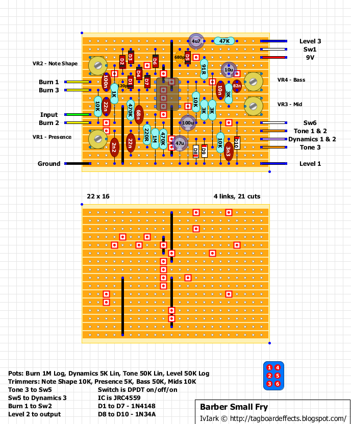
The most recent of the two schems is correct. The toggle switch is on/off/on, left to right it's: 4 symetrical clippers in loop, 7 clippers in loop, 7 clippers in loop and 1 ge to ground. The bass, mid, presence, and note shape are trim pots.
-
Mbas974
- Resistor Ronker
Concerning the hard-clipping section, how much big should be the POT for having NO CLIP at all (larger I see around is 10K..) ??
I'd like using this POT like a switch also...
Tx
I'd like using this POT like a switch also...
Tx
-
IvIark
- Tube Twister
Information
Verified:
"If anyone is a 'genius' for putting jacks in such a pedal in the only spot where they could physically fit, then I assume I too am a genius for correctly inserting my legs into my pants this morning." - candletears7 - TGP
Thank you very much for sharing the schematic, that is very useful.
I have recently acquired the dual channel version (the Burn Unit EQ) and found that it sounds quite different to the Small Fry. One of the differences is that the Burn Unit has a 25k mid pot which allows for much more midrange. The second noticeable difference is the presence resistor to Vcc - 220 in the Small Fry vs. 470 in the Burn Unit. Both changes make the Burn Unit sound warmer and smoother.
I then did the following mods to my Small Fry:
1) Inserted a 10k resistor between the mid pot and the 3k resistor which is connected to the bass pot. So instead of a variable resistance of 3k to 13k I have now 13k to 23k. The lowest setting is now equal to the highest setting before the mod while the highest setting goes far beyond.
2) Inserted another 220 resistor in the presence line, which is like turning the presence control down a notch.
The modded Small Fry now sounds a lot closer to the Burn Unit, even though it is still a bit brighter but it's no longer too bright.
These are the mods I could do without taking the whole thing apart. Of course it would have been best to change the 10k trimmer to a 25k one for the most possible range.
Cheers Stephan
Heya,
I'm a newbie when it comes to these things but I have a hard time understanding some things here. On the original Small Fry the Tone Pot just has two lugs connected to the circuit (3 & 2) and the dynamics pot as well (although different ones 2 & 1) and on the veroboard layout (and the schematic) all lugs of the pots are used. Am I missing something here or are these schematics not 100% correct?
And another question: regarding the clipping switch: does the "wire" from lug 1 of the switch have a connection to both diode arrays or just the lower one with D7, D6 and D5? In the schematic the lower one with the three diodes is connected to the switch between D6 & D5 (indicated by the black dot) but in between D2 and D3 there's no dot. From what I understand this would mean there's no connection. But when looking at the veroboard layout there seems to be a connection (which seems logical - but there's no dot in the schematic).
And another question would be regarding the Resistor (91) which is connected between the 9V source and V+ in this schematic. Which effect does that have? Would that decrease the voltage going to the IC? I realize that VCC is acting as the virtual ground / bias for the circuit which usually is 4.5V in most pedals as far as I understand, but on most other schematics I have seen, there was no resistor inbetween the Battery/DCjack and the IC - and looking on Dave's LTD schematic there's no V+ just 9V and / 4.5V as I would have expected.
Just honestly trying to understand these things... as I said... I'm a total noob trying to get my head around these things.
mully
-
dv8r601
- Breadboard Brother
mully wrote:Heya,
I'm a newbie when it comes to these things but I have a hard time understanding some things here. On the original Small Fry the Tone Pot just has two lugs connected to the circuit (3 & 2) and the dynamics pot as well (although different ones 2 & 1) and on the veroboard layout (and the schematic) all lugs of the pots are used. Am I missing something here or are these schematics not 100% correct?
And another question: regarding the clipping switch: does the "wire" from lug 1 of the switch have a connection to both diode arrays or just the lower one with D7, D6 and D5? In the schematic the lower one with the three diodes is connected to the switch between D6 & D5 (indicated by the black dot) but in between D2 and D3 there's no dot. From what I understand this would mean there's no connection. But when looking at the veroboard layout there seems to be a connection (which seems logical - but there's no dot in the schematic).
And another question would be regarding the Resistor (91) which is connected between the 9V source and V+ in this schematic. Which effect does that have? Would that decrease the voltage going to the IC? I realize that VCC is acting as the virtual ground / bias for the circuit which usually is 4.5V in most pedals as far as I understand, but on most other schematics I have seen, there was no resistor inbetween the Battery/DCjack and the IC - and looking on Dave's LTD schematic there's no V+ just 9V and / 4.5V as I would have expected.
Just honestly trying to understand these things... as I said... I'm a total noob trying to get my head around these things.
mully
The Pots have their lugs tied together(2 wires from board 1 is to lug 3, 1 to lugs 2&3) the vero layout works as I've made it twice before now.
Clipping switch: lug 1 just switches in the 680p, D5,6,2,3; Lug2 to gain pot lug1(burn); lug3 not used; lug 4 not used; lug 5 to both warp pot3(dynamics) and tone pot3; lug 6 to the 1n34a from gnd. so when its up only 5-6 connect and down 1-2 connect. easy peasy but confusing as shit the first time building it.
And the 91r resistor is just there as part of the power supply noise filter, it makes a low pass in conjunction with 100uF cap. anything up to about 250 ohms will be enough to filter out any 60hz noise without cutting voltage too terribly much
I'm just wondering why since the pots on the original are wired differentlydv8r601 wrote:The Pots have their lugs tied together(2 wires from board 1 is to lug 3, 1 to lugs 2&3) the vero layout works as I've made it twice before now.

-
dv8r601
- Breadboard Brother
It does the same thing I just prefer to tie them together. Its a variable resistor that's all. Great pedal btw. And Mr barber is a champion among men that helps the DIY community when he can like Brian Wampler and Paul Cochrane so buy his pedals from him if you can. They are priced great
oh I know I have had several Barber pedals (Barb EQ, Custom Cool, Unlimited, Small Fry, Gain Changer, Direct Drive, Tone Press, Trifecta, Dirty Bomb) and all of them can compete with the best. The small fry is one of my all time favourite overdrives (next to the San B Overdrive by Push+Pull) and I just want to make a eyelet board version of it. Just for myself. And I'm thinking why not start with the best.... it can't be that much more difficult than a fuzz face....dv8r601 wrote:It does the same thing I just prefer to tie them together. Its a variable resistor that's all. Great pedal btw. And Mr barber is a champion among men that helps the DIY community when he can like Brian Wampler and Paul Cochrane so buy his pedals from him if you can. They are priced great