Mr.TYR
What do you intend to do? Sell your gadget or share information?
Solo Dallas - SVDS Replica [traced]
-
EddieTavares

- Breadboard Brother
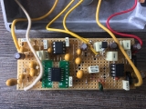
my last proto :
https://www.casimages.com/img.php?i=180 ... 665960.jpg
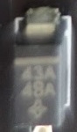
for the rev3 like my prototype the " diode" 43a 48a is the key , i don't have fond a good alternative at the moment but i try ^^
i have used Schottky diode like mbr 150 and 1n5817 to try it seem to work but not perfect at the moment
maybe a zener + a schottky diode lol
i will test to find that
https://www.casimages.com/img.php?i=180 ... 665960.jpg
for the rev3 like my prototype the " diode" 43a 48a is the key , i don't have fond a good alternative at the moment but i try ^^
i have used Schottky diode like mbr 150 and 1n5817 to try it seem to work but not perfect at the moment
maybe a zener + a schottky diode lol
i will test to find that
there is the work of patrice and me 
tsr rev 3
traces :


last schematic:

last layout :

last components list:

at the moment i don t have the good equivalent to the coponent d3
what do you think ?
pic of d3 :
tsr rev 3
traces :


last schematic:

last layout :

last components list:

at the moment i don t have the good equivalent to the coponent d3
what do you think ?
pic of d3 :

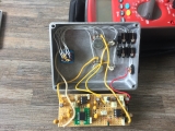
inside my proto :


Information
- Posts: 42
- Joined: 28 Mar 2012, 14:00
- my favorite amplifier: 1986 Gallien-Krueger 400RB
- Completed builds: BYOC 2-knob compressor
Klon Buffer
Devi Ever Ruby, OK, Hyperion
EP-boost->Modded SD1
Meathead
Hunny Bunny
Roger Mayer Voodoo Bass (excellent)
Zendrive
Big Muffs (Russian, P19, Jordan Creator, Jumbo Tonebender)
Lots of other miscellaneous pedals that aren't worth mentionin - Location: MA, US
- Has thanked: 7 times
- Been thanked: 6 times
- Contact:
I don't think 10nF is right for C7. That creates a lowpass filter and completely destroys the pre-emphasis. I think 100pF is right.
i've built this with boby6kiler's latest layout, changing c7 to 100pf as triplesevener suggusted, it does work and sound good, but im also stuck on the D3 diode. There is a bit of hiss in the sound without the D3 diode connected, i've tried a few diodes that i have on hand, no difference with 1n4148, 1n4742, 1n4749, 1n4004, 1n5817, sr560. I did have partial success with a 1n4739, but it heats up and blows within about 20 seconds, but it does remove the hiss and work properly temporarily. I tried running it on 9v and it is hiss free without D3 in the circuit, its a bit more compressed than running at 12v but still very usable. I've got 1n4761 on order so ill try one of those when they arrive. Anyone have any ideas on the value of the D3 diode?
-
marshmellow

- Cap Cooler
Leave it out. That power supply section drawing is a mess. If it's a standard silicon or schottky diode, it doesn't do anything. If it is a zener, then the 10R resistor is definitely wrong. I don't see any reason why the supply voltage should be dropped at that point. It will run fine on 9V or 12V.
-
EddieTavares
- Breadboard Brother
nkay24, marshmellow
The ps section emulates the same voltages as the transmitter (9v battery supply) and the the receiver (12v internal ps), however, they could not simulate the first NE570 half at 9v and the other half at 12v... Probably it does not affect the final result.
The ps section emulates the same voltages as the transmitter (9v battery supply) and the the receiver (12v internal ps), however, they could not simulate the first NE570 half at 9v and the other half at 12v... Probably it does not affect the final result.
i have do the same work in rev 2 with pics and infos
if someone want to work on it tell me i can post here
the rev 2 sound good ,more bassy then my proto of rev3
i have send all to apollo long time ago to try but no news
we need just 4 ou 5 values of component all the rest is verified
if someone want to work on it tell me i can post here
the rev 2 sound good ,more bassy then my proto of rev3
i have send all to apollo long time ago to try but no news
we need just 4 ou 5 values of component all the rest is verified
-
ppluis0

- Diode Debunker
Hello boys,
It is not my intention to bother with the great development that you are doing here, but I think we are being deceived by the gossip of the manufacturer of this replica about the need or the "magic" of including a compandor IC.
The need to compress and expand the audio signal is to improve wireless transmission, but if the idea is to reduce this to pedal format it would not be necessary to do this process.
Think that the system is an FM transmitter (on the player's guitar belt) plus two channel receiver, and solely the audio path are "replicated":
I imagine that the purpose of use an LM388 was to drive a transformer to deal with the XLR output
Look at the trannie near that power audio chip at the bottom right of this image:

If we analyze the circuit already obtained we could completely eliminate the SA571, join with a wire the legs 6 and 10 at the socket of that chip. In this way we will have an opamp handling the input of a 2W audio chip, which would resemble all this to a Lovepedal Black Magic, Jubilee or the like, but using different audio amp than the LM386.
Perhaps the "magic" reside only in the buffering action of this chip without have to drive an loudspeaker ??
Cheers,
Jose
It is not my intention to bother with the great development that you are doing here, but I think we are being deceived by the gossip of the manufacturer of this replica about the need or the "magic" of including a compandor IC.
The need to compress and expand the audio signal is to improve wireless transmission, but if the idea is to reduce this to pedal format it would not be necessary to do this process.
Think that the system is an FM transmitter (on the player's guitar belt) plus two channel receiver, and solely the audio path are "replicated":
I imagine that the purpose of use an LM388 was to drive a transformer to deal with the XLR output
Look at the trannie near that power audio chip at the bottom right of this image:
If we analyze the circuit already obtained we could completely eliminate the SA571, join with a wire the legs 6 and 10 at the socket of that chip. In this way we will have an opamp handling the input of a 2W audio chip, which would resemble all this to a Lovepedal Black Magic, Jubilee or the like, but using different audio amp than the LM386.
Perhaps the "magic" reside only in the buffering action of this chip without have to drive an loudspeaker ??
Cheers,
Jose
-
EddieTavares
- Breadboard Brother
ppluis0
Do you tried one?
Do you tried one?
-
ppluis0
- Diode Debunker
Saudações Eddie,
Just discover this thread today and search the web about read more on this replica. I'm currently involved in other time consuming projects, but will breadboard the schematic discussed here ASAP to see what can hear.
I'm in doubt that the use of a compressor-expander IC merely chained as this manufacturer does -with the surrounding passive component values that appear in the schematic- make the desired sound.
If in the mentioned chip at one of the boards already built and running by participants of this thread can be tied its input and output pins to the outer tabs of a spdt and from the central contact feed the LM380 with a pre or post processed signal, we can confirm the need (or redundancy) to place a compander at the flip of this switch.
I hope to read what Mictester think about this subject, due their expertise employing this IC's
Cheers,
Jose
-
EddieTavares
- Breadboard Brother
Bom dia Zé.
SVDS is a mic wirelless system modified to work with guitar.
Something that I realise when I was teenager comparing some wireless mic and wired ones: when we expand a compressed signal it does not sound always like the original signal, it sounds more like a compressor in addiction it bossts some frequencies.
I breadboarded that circuit various arrangements and I have no doubt that the heart of that circuit is the compander chip, I tried a IC gain stage (tl072 like mxr microamp), LM386 and LM380 in the output booster with almost no difference.
Grande abraço.
Thank you very much for all your hard work on this project! I was looking for infos like those since longer time. So I was really glad to find rhis thread!boby6kiler wrote:there is the work of patrice and me
tsr rev 3
traces :
[…]
last schematic:
[…]
last layout :
[…]
last components list:
[…]
at the moment i don t have the good equivalent to the coponent d3
what do you think ?
pic of d3 :
[…]
But the image links in this post are all broken is there a chance you could re-post them? Or send them via PM? That’d be awesome!!
Thank you very much!
Christian
sound very good to me ,close to the original but some components are unverified
Hi there!
I just want to thank you for the effort put into reverse-engineering of the device.
Just want to ask has anybody figured out how has been made an optical limiter aka snap potentiometer? boby6kiler how do you know was NSL32 optocoupler used in original replica?
I just want to thank you for the effort put into reverse-engineering of the device.
Just want to ask has anybody figured out how has been made an optical limiter aka snap potentiometer? boby6kiler how do you know was NSL32 optocoupler used in original replica?