Nope. At least not in the one I just got. TL072 op-amp, red LED's for clipping and not my cup of tea. Anyone need any pics before I flip this?patafix wrote:Isn't there some MAX1044 in this ???
The PCB glued and gooped to the footswitch makes me think of a voltage doubling circuit.
HAO - Sole Pressure [traced]
-
The Rotagilla

- Diode Debunker
The television will not be revolutionized.
-
nooneknows

- Resistor Ronker
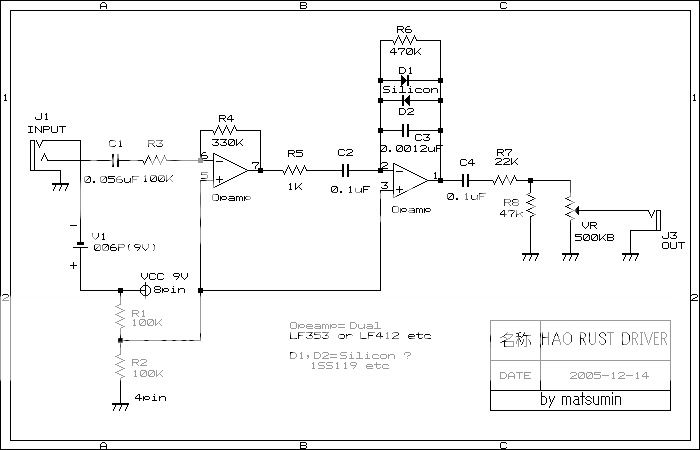
if the Sole Pressure is a variation of the Rust Driver circuit and this schematics for the Rust Driver is correct:smanq wrote:From some posts and what we can see from the guts, the schematics could be like this
https://i14.photobucket.com/albums/a303 ... IVER-1.jpg
the diodes appear to be in a wrong position.
Anyone can confirm?
thx
Hey, I bet you made a trade for that Sole Pressure didn't ya. And the board was already de-gooped when you got it?The Rotagilla wrote:Nope. At least not in the one I just got. TL072 op-amp, red LED's for clipping and not my cup of tea. Anyone need any pics before I flip this?patafix wrote:Isn't there some MAX1044 in this ???
The PCB glued and gooped to the footswitch makes me think of a voltage doubling circuit.
Funny meeting you here.
-
The Rotagilla
- Diode Debunker
Oh snap!jaydawg wrote:Hey, I bet you made a trade for that Sole Pressure didn't ya. And the board was already de-gooped when you got it?The Rotagilla wrote:Nope. At least not in the one I just got. TL072 op-amp, red LED's for clipping and not my cup of tea. Anyone need any pics before I flip this?patafix wrote:Isn't there some MAX1044 in this ???
The PCB glued and gooped to the footswitch makes me think of a voltage doubling circuit.
Funny meeting you here.
It's on its way down the road again.
The television will not be revolutionized.
-
rhandy gaye

- Solder Soldier
hi,
i only quickly read this thread but there seems to be confusion about the the use of a max1044.
the links to pics at the start of the thread are of a modded sole pressure by a japanese fx mod/tweaker (soul power instrumnents).
cheers.
i only quickly read this thread but there seems to be confusion about the the use of a max1044.
the links to pics at the start of the thread are of a modded sole pressure by a japanese fx mod/tweaker (soul power instrumnents).
cheers.
-
new_anuzzerone

- Breadboard Brother
patafix wrote:Isn't there some MAX1044 in this ???
The PCB glued and gooped to the footswitch makes me think of a voltage doubling circuit.
sorry for continuing an old thread:
Opened my sole pressure and there was only a drop of goop on the IC, it came of with a pocket knife
underneath there is a: ST (http://www.st.com) --> manufact. --> TL0720N
tried to find some datasheets, but negative.
some chinese salesmen seem to sell these.
Maybe it helps.
-
FiveseveN

- Cap Cooler
Information
I think it's TL072CN, C indicating normal temp range and N DIP8.
http://www.datasheetcatalog.org/datashe ... s/2298.pdf
http://www.datasheetcatalog.org/datashe ... s/2298.pdf
Ignorance more frequently begets confidence than does knowledge. (Charles Darwin)
-
IvIark
- Tube Twister
Information
This has reminded me that I've got one of these somewhere that I haven't had a proper look at yet. I'll do it over the next few days and post a schematic.
"If anyone is a 'genius' for putting jacks in such a pedal in the only spot where they could physically fit, then I assume I too am a genius for correctly inserting my legs into my pants this morning." - candletears7 - TGP
-
new_anuzzerone
- Breadboard Brother
Yep, you´re right. Was difficult to see, coz the goop nearly stripped of all the script / paint of the TL.FiveseveN wrote:I think it's TL072CN, C indicating normal temp range and N DIP8.
http://www.datasheetcatalog.org/datashe ... s/2298.pdf
With daylight, it´s easier. It´s an 072CN
added a quick gut shot of mine
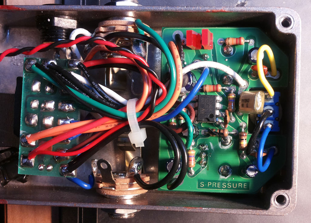
cheers
-
new_anuzzerone
- Breadboard Brother
Homework? DONE!
Here´s some other pics.
The values given, are the ones I measured from the resistors (no, this isn´t a 22k / 5% resistor...)
The 2 diodes on the bottom are just difficult to read: 44R and 5B (I don´t know, if that´s right...)
the pots are:
level:
10 4B
35 1V
Drive:
50 4C
33 6V
whatever that means (100k B and 500k C ??)
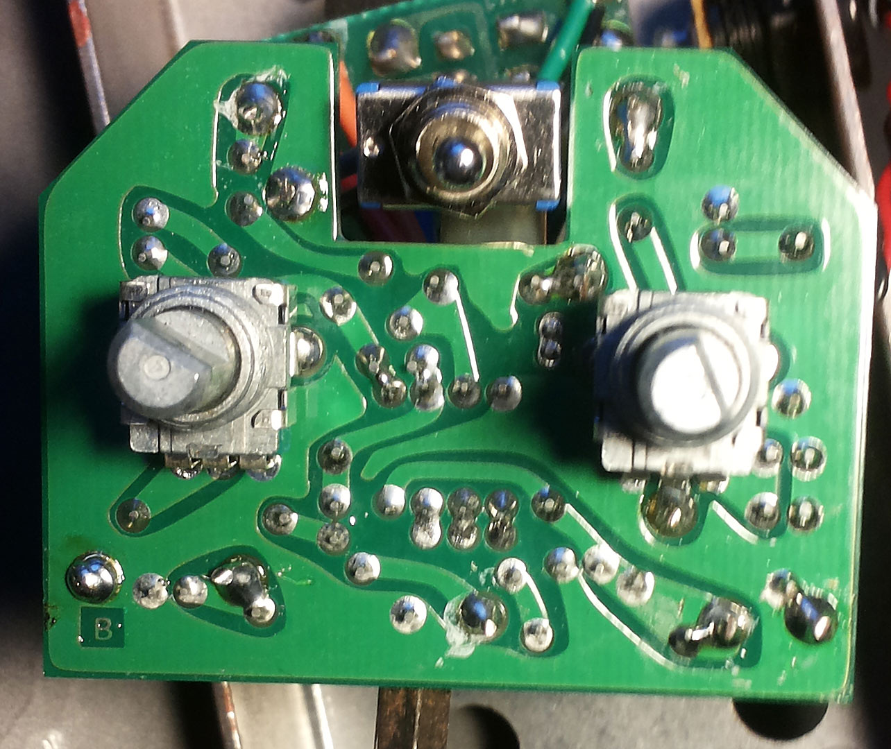
the switch is a on-off-on
the board, where the FS is mounted, holds only the LED on the other side, no parts there
ok, here´s the pics:
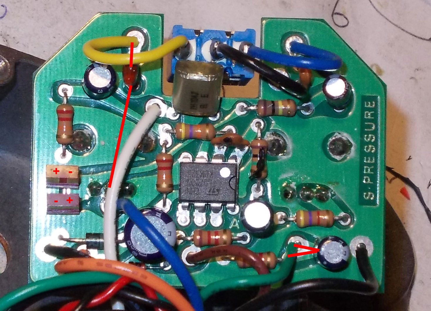
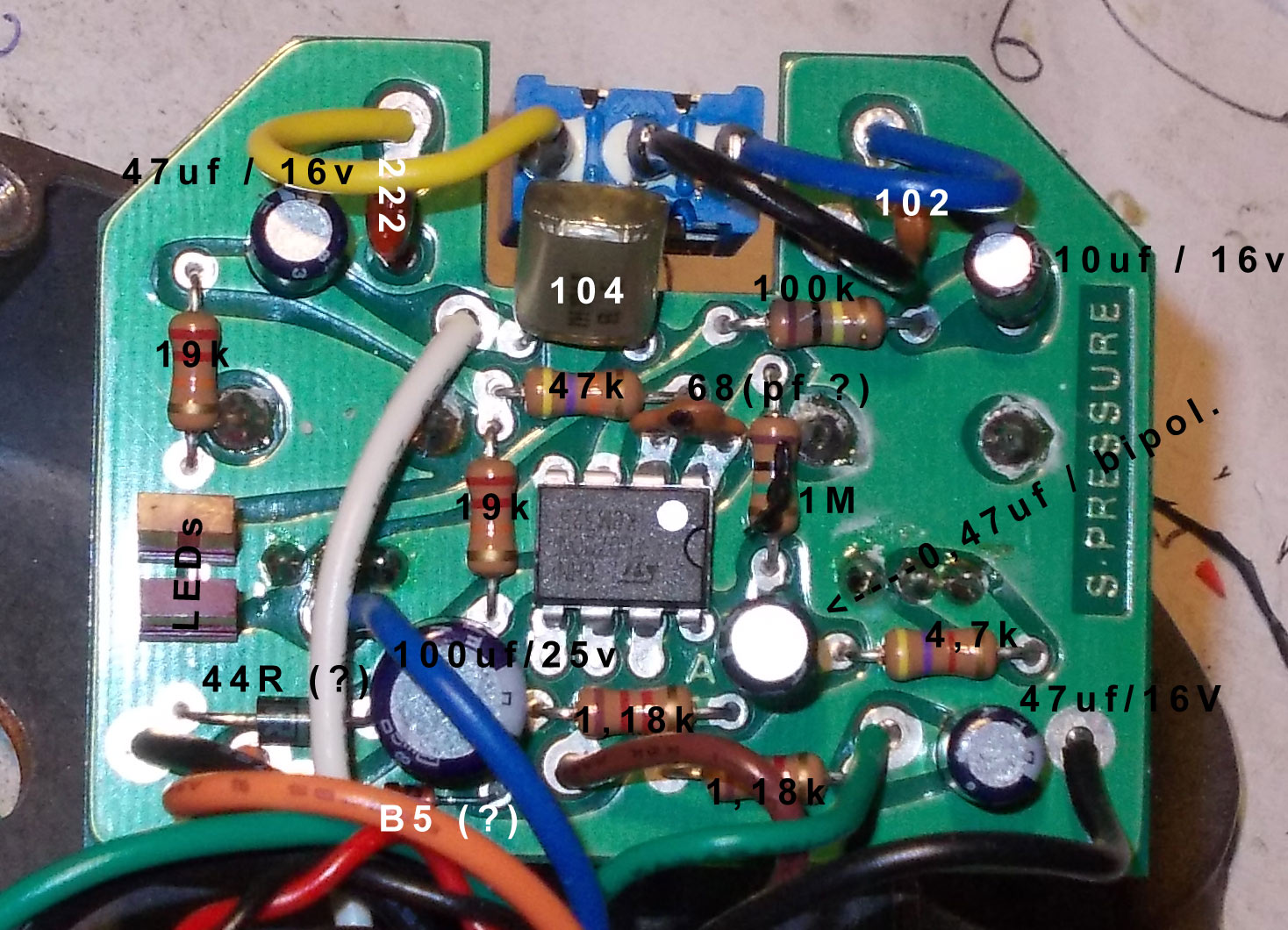
sorry, for the blurry pics
regards
Here´s some other pics.
The values given, are the ones I measured from the resistors (no, this isn´t a 22k / 5% resistor...)
The 2 diodes on the bottom are just difficult to read: 44R and 5B (I don´t know, if that´s right...)
the pots are:
level:
10 4B
35 1V
Drive:
50 4C
33 6V
whatever that means (100k B and 500k C ??)
the switch is a on-off-on
the board, where the FS is mounted, holds only the LED on the other side, no parts there
ok, here´s the pics:
sorry, for the blurry pics
regards
-
Manfred
- Tube Twister
Information
- Posts: 1945
- Joined: 04 Apr 2009, 23:42
- Has thanked: 1675 times
- Been thanked: 1360 times
I excerpted follwing schematic from the shots and the schematic from above.smanq wrote:From some posts and what we can see from the guts, the schematics could be like this The supply filter seems a 100uF cap.
I suppose the VR is half supply from classic 2 resistors and a filter cap (values?).
Where are placed the 22K and 100K resistors we can see in photos?
Please try to comment or complete it (errors, values, missing components, ...)
Corrected schematic HAO Sole Pressure
The LEDs are seriell connected to a large 100k resistor,
this leads to the conclusion that the LEDs must be low current types.
What are the values of the potentiometers?
I suppose that the unidentified part of the schematic act as noiseless indicating LED switching.
-
Manfred
- Tube Twister
Information
- Posts: 1945
- Joined: 04 Apr 2009, 23:42
- Has thanked: 1675 times
- Been thanked: 1360 times
Very strange the choice of 100K resistor before the LEDs, I've never seen a such high value in this position.
For the pots, I think the Drive is C500K (rev log) and the Volume is A100K (log).
You can delete the other components from the schematics: they are for the switch.
For the pots, I think the Drive is C500K (rev log) and the Volume is A100K (log).
You can delete the other components from the schematics: they are for the switch.
-
Manfred
- Tube Twister
Information
- Posts: 1945
- Joined: 04 Apr 2009, 23:42
- Has thanked: 1675 times
- Been thanked: 1360 times
It is indeed an extraordinary high resistance.smanq wrote:Very strange the choice of 100K resistor before the LEDs, I've never seen a such high value in this position.
For the pots, I think the Drive is C500K (rev log) and the Volume is A100K (log).
You can delete the other components from the schematics: they are for the switch.
The expected current value which feed the LED while the maximum signal half-wave is about 40 Microamps.
I don't know how the LED clipping in this case is.
Maybe the main clipping comes from the OP-Amp.
I modified the schematic following your recommandation:
Corrected schematic HAO Sole Pressure
-
Manfred
- Tube Twister
Information
- Posts: 1945
- Joined: 04 Apr 2009, 23:42
- Has thanked: 1675 times
- Been thanked: 1360 times
I bought a second hand one and dissected it.
So I could I traced the Clipping LEDs Curves.
The LEDs are matched.
I verified the circuit and found that the capacitor in seriell with the drive pot has a value of 0.47uF.
I add some oszilloscope shots.
I fed the input with a sine wave of 50 Millivolts 1000 cps.
The Clipping LEDs flatten the sine wave soft so as a slightly overdriven tube power amp.
The clipping starts at the 3 o'clock position of the drive pot in that signal input.
The Op-amp clipping starts a bit greater than the 3 o'clock position.
The Op-amp clipping has been read on pin 1.
Corrected schematic HAO Sole Pressure
-
box
- Breadboard Brother
Hi,Manfred wrote:I was wrong.
Here the corrected Schematic:
Please check IC pins are not correct.
TL072 is dual OP-amp :
pins 1,2,3,4 are correct(4-Gnd).
pins 5,6,7 -NC
pin 8 --Vcc.
Rgds,
box
-
Manfred
- Tube Twister
Information
- Posts: 1945
- Joined: 04 Apr 2009, 23:42
- Has thanked: 1675 times
- Been thanked: 1360 times
Hi Box,
thanks for the hint.
thanks for the hint.
Great thread, lots of info on this pedal here, thanks!
So let's say, hypothetically, one had a pedal such as this (I have this friend...lol) with the TL072CN, is there a way to brighten this thing up a bit? I know, I know...it's supposed to sound like a BASSman, but good gawd, ya'll! Too dark!! Would using a "brighter" IC do the trick? I know the TL072 can be a little dark and gritty (part of its charm). Would the BB or more hi-fi equivalent achieve the desired objective? Not trying to start another opamp debate...
However, any thoughts and/or feedback would be greatly appreciated!!! Thanks!
-
Manfred
- Tube Twister
Information
- Posts: 1945
- Joined: 04 Apr 2009, 23:42
- Has thanked: 1675 times
- Been thanked: 1360 times
Try by reducing the input capacitor (100nF).lemonengine1 wrote:Great thread, lots of info on this pedal here, thanks!
So let's say, hypothetically, one had a pedal such as this (I have this friend...lol) with the TL072CN, is there a way to brighten this thing up a bit? I know, I know...it's supposed to sound like a BASSman, but good gawd, ya'll! Too dark!! Would using a "brighter" IC do the trick? I know the TL072 can be a little dark and gritty (part of its charm). Would the BB or more hi-fi equivalent achieve the desired objective? Not trying to start another opamp debate...
However, any thoughts and/or feedback would be greatly appreciated!!! Thanks!