germanium Fuzz Face with some mods. I have heard some great Doom/Stoner sound coming from this pedal. I started to collect some pictures and trying to pull the values from them. Anyone interested in helping?
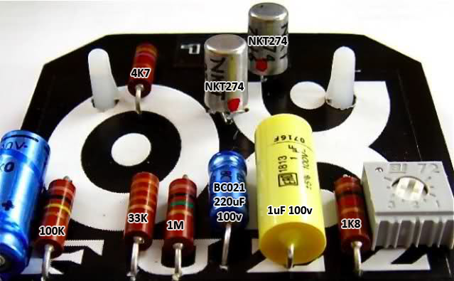
Oxfuzz is pretty much standard fuzz face, but with 470R bumped to 1K for more output and increased output cap from 10nF to 100nF for more low end. Rest has standard fuzz face values. Volume pot can be 250K or 100K as far as i remember. 4k7 resistor is for led. 1m is antipop dropdown resistor
Oxfuzz is pretty much standard fuzz face, but with 470R bumped to 1K for more output and increased output cap from 10nF to 100nF for more low end. Rest has standard fuzz face values. Volume pot can be 250K or 100K as far as i remember. 4k7 resistor is for led. 1m is antipop dropdown resistor
I understand that its a basic Fuzz Face with a trimmer but.. You say that the 10nF cap was increased to 100nF but I take it that the 2 blue caps are electrolytics and the yellow clearly states 1uF on it so am I missing something or maybe you meant 10uF to 100uF. I did find a better picture online that shows the cap next to 1M pull down to be a 2.2uF.
BOM so far is: Left to right
Unknown cap
100K
33K
1M
2.2uF
1uF
1K
10K Trimmer ?
4.7K CLR
Q1 NKT274 or NKT275
Q2 NKT274 or NKT275
Well that totally makes sense now. That's where the 100n came from. Man I have a lot to learn about reversing a pedal. I still need to figure out what the other cap is. Back to the interwebs for more schematic comparisons.
Ken from the psych/doom/blues band Sons Of Otis builds these. Their earlier albums are quite good but they're more doom than psych and blues these days, not really my thing. He has always had fantastic tone and plays 70s Japanese guitars out of a 70s Orange OR-120.
I had two Oxfuzzes (Ge and Si) and in both input caps were 2.2uF and 100nF as output cap, but I've seen gutshots with output cap 10nF and even 1uF, too.
beedotman wrote:I had two Oxfuzzes (Ge and Si) and in both input caps were 2.2uF and 100nF as output cap, but I've seen gutshots with output cap 10nF and even 1uF, too.
Whould you know what would make a "dark" model of these. I wonder if its just a matter of output cap to allow crazy lowend. Ideas?
beedotman wrote:I had two Oxfuzzes (Ge and Si) and in both input caps were 2.2uF and 100nF as output cap, but I've seen gutshots with output cap 10nF and even 1uF, too.
Whould you know what would make a "dark" model of these. I wonder if its just a matter of output cap to allow crazy lowend. Ideas?
I'm not sure but I think input and output caps could were increased in "dark" version - 4u7 for input and 1u for output?
Does anybody have Oxfuzz Hybrid and can check what transistor type is used for Q1?
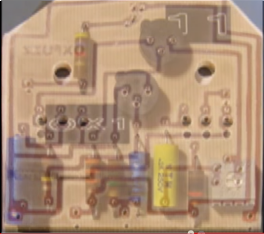
I know that are two versions for sure - orange one with NKT275 for Q2 and plastic transistor for Q1 and violet one, currently made - with NKT274 for Q2 and metal can trannie for Q1.
I could find only those two pics.
NKT275 have marking 152, so it could be hfe for Q2.
Attachments
ox_hybrid_nkt274.jpg (59.81 KiB) Viewed 3249 times
ox_hybrid_nkt275.jpg (52.17 KiB) Viewed 3249 times
I see two errors:
# Emiter of Q1 connected to 1M is not connecteted to ground
# 100K resistor connected to Q1 Base on other side should be connected to Emiter of Q2 and lug 3 of Fuzz pot
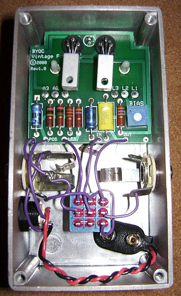
layout of oxfuzz is almost the same as byoc fuzz face, I cannot find layout for it, but I'm sure that it is somewhere online...
beedotman wrote:I see two errors:
# Emiter of Q1 connected to 1M is not connecteted to ground
# 100K resistor connected to Q1 Base on other side should be connected to Emiter of Q2 and lug 3 of Fuzz pot
layout of oxfuzz is almost the same as byoc fuzz face, I cannot find layout for it, but I'm sure that it is somewhere online...
[ Image ]
Thanks I see it, great; this is the lay corrected; the electros ones are the real values??
now it looks fine to me.
electro cap values are fine - ox is using standard fuzz face values, but for input cap I prefer smaller cap values - 1uF or even something between 100nf-470nf
