 tight metal -3a.sch
- (117.06 KiB) Downloaded 278 times
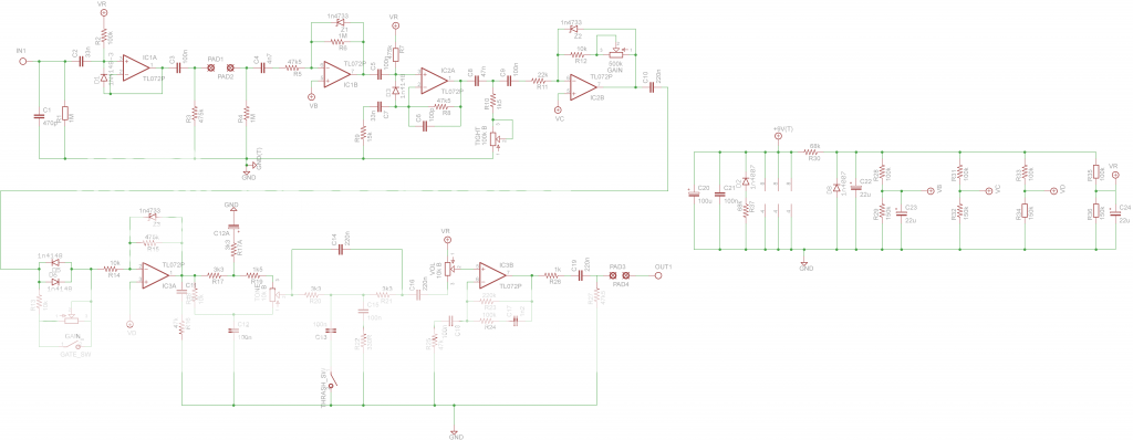
Amptweaker - Tight Metal [traced]
-
bajaman

- Old Solderhand
Information
- Posts: 4549
- Joined: 26 Jun 2007, 21:18
- Location: New Brighton, Christchurch, NZ
- Has thanked: 596 times
- Been thanked: 2061 times
my preliminary amended Eagle schematic - tone control, notch filter and power supply corrected 
be kind to all animals - especially human beings
-
apollomusicservice

- Resistor Ronker
Information
Bajaman can you upload your schematic as pdf?
-
bajaman
- Old Solderhand
Information
- Posts: 4549
- Joined: 26 Jun 2007, 21:18
- Location: New Brighton, Christchurch, NZ
- Has thanked: 596 times
- Been thanked: 2061 times
be kind to all animals - especially human beings

-
jymaze

- Resistor Ronker
Thanks you all for putting the schematic from my crappy handwritten drafts in a software. I just hate doing it for some reason. But I can trace all day long! That is the fun part for me.
-
azrael

- Cap Cooler
Was just waiting until the correction were released.J0K3RX wrote:What, nobody made a single layer through hole yet?Is it because it doesn't have Wampler tattooed on it?
Don't make me do it! We will be debugging till the cows come home...
I'll finish it after work today. Just a bit hard to make out what's going on with the power network, I usually prefer to use Net labels or Voltage reference symbols for that sort of thing, so it was a bit harder for me to decipher it.
-
apollomusicservice
- Resistor Ronker
Information
This is a new version with implemented corrections. Points 1-5 are connected to ground, IN-input, OUT-output, IN1 and OUT1 to insert out, the T1 Tight pot, G1 and G2 to gain pot, G3 and G4 to gain pot other sections (both at Gate SW also), TO1 TO2 TO3 on Tone pot, TH on Thrash sw, V1 V2 V3 the Volume pot and
+9 V power supply.
+9 V power supply.
-
bajaman
- Old Solderhand
Information
- Posts: 4549
- Joined: 26 Jun 2007, 21:18
- Location: New Brighton, Christchurch, NZ
- Has thanked: 596 times
- Been thanked: 2061 times
be kind to all animals - especially human beings
-
bajaman
- Old Solderhand
Information
- Posts: 4549
- Joined: 26 Jun 2007, 21:18
- Location: New Brighton, Christchurch, NZ
- Has thanked: 596 times
- Been thanked: 2061 times
- Tight Metal 0.9 (needs verifying) small.BMP (1.72 MiB) Viewed 2454 times
I will post complete files including gerber files etc. once layout is deemed to be correct - I will probably adjust the dc socket footprint for a 2.1 mm standard DC socket in the final draft.
here is a composite of V0.9
cheers
bajaman
be kind to all animals - especially human beings
-
J0K3RX

- Degoop Doctor
azrael wrote:Was just waiting until the correction were released.J0K3RX wrote:What, nobody made a single layer through hole yet?
Don't make me do it! We will be debugging till the cows come home...
I'll finish it after work today. Just a bit hard to make out what's going on with the power network, I usually prefer to use Net labels or Voltage reference symbols for that sort of thing, so it was a bit harder for me to decipher it.
Damn! Can't wait!!
-
bajaman
- Old Solderhand
Information
- Posts: 4549
- Joined: 26 Jun 2007, 21:18
- Location: New Brighton, Christchurch, NZ
- Has thanked: 596 times
- Been thanked: 2061 times
- Amptweaker - Tight Metal V5
be kind to all animals - especially human beings
-
euronymous0001
- Breadboard Brother
im not accustomed to the way bajaman drew the PSU. 
so here is one for those who are like me
so here is one for those who are like me
-
bajaman
- Old Solderhand
Information
- Posts: 4549
- Joined: 26 Jun 2007, 21:18
- Location: New Brighton, Christchurch, NZ
- Has thanked: 596 times
- Been thanked: 2061 times
Can you do double sided etching okay Jim 
and you may not like my latest schematic euronymous0001 but at least it is correct - your one has at least two errors in the layout and component values ( and it is almost too small to read
  ) hint 15k resistor should be 1k5 and the second filter to ground in the notch section is connected wrong
bajaman
and you may not like my latest schematic euronymous0001 but at least it is correct - your one has at least two errors in the layout and component values
bajaman
be kind to all animals - especially human beings
-
bajaman
- Old Solderhand
Information
- Posts: 4549
- Joined: 26 Jun 2007, 21:18
- Location: New Brighton, Christchurch, NZ
- Has thanked: 596 times
- Been thanked: 2061 times
AND the 68k resistor supplying the bias line should be 6k8
be kind to all animals - especially human beings
-
bajaman
- Old Solderhand
Information
- Posts: 4549
- Joined: 26 Jun 2007, 21:18
- Location: New Brighton, Christchurch, NZ
- Has thanked: 596 times
- Been thanked: 2061 times
AND the VR supply rail resistors are 18k and 47k NOT 100k and 150k
be kind to all animals - especially human beings
-
bajaman
- Old Solderhand
Information
- Posts: 4549
- Joined: 26 Jun 2007, 21:18
- Location: New Brighton, Christchurch, NZ
- Has thanked: 596 times
- Been thanked: 2061 times
AND the resistor in series with D2 should be 47 ohm NOT 68k
be kind to all animals - especially human beings
-
bajaman
- Old Solderhand
Information
- Posts: 4549
- Joined: 26 Jun 2007, 21:18
- Location: New Brighton, Christchurch, NZ
- Has thanked: 596 times
- Been thanked: 2061 times
AND C14 should be 22n NOT 220n - for fuck's sake use your eyes
be kind to all animals - especially human beings