Dumbloid  [traced]

General documentation, gut shot, schematic links, ongoing circuit tracing, deep thoughts ... all about boutique stompboxes.
User avatar
The G
Grease Monkey
Information
Posts: 559
Joined: 21 Jun 2009, 11:43
Location: Bucharest, Romania
Has thanked: 408 times
Been thanked: 285 times

Post by The G »

juansolo wrote:No urge to build one... Does anyone actually like the sound of op-amp clipping?
I do. Op amp clipping is far more common than you think. Even if it's followed by diodes or whatever different clipping stages, op amp clipping still contributes a lot to the final sound. Some examples are Proco Rat, Marshall Guv'nor, Boss Metal Zone and other Boss distortions, Barber Electronics Dirty Bomb, G2D Morpheus, MI Audio Crunch Box and Tube Zone, Suhr Riot, and even the Klon Centaur at max gain. Then there are Sansmap Classic and GT2, Crowther Hotcake and Okko Dominator, which rely solely on op amp clipping.
What I don't like at op amp clipping is the ugly jitter when the voltage borders the clipping threshold and the sudden transition from clipped to non-clipped and vice versa.
Cannibal wrote:The biasing resistor of the first buffer is only 150k, this thing has a pretty low input impedence. Do you think that's a deliberate choice or just a mistake by the "designer"?
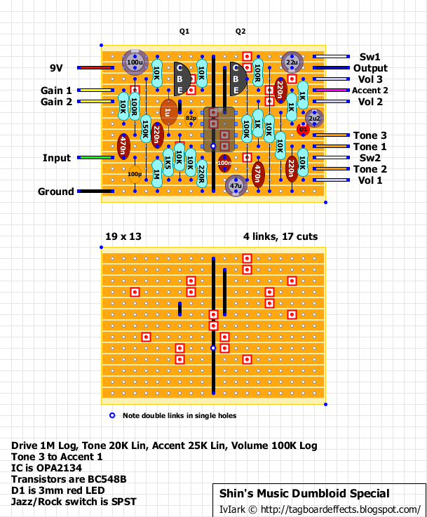
Could be deliberate, to shave some highs if you guitar has passive pickups.

User avatar
MoonWatcher
Diode Debunker
Information
Posts: 715
Joined: 28 Jul 2008, 12:27
Has thanked: 40 times
Been thanked: 52 times

Post by MoonWatcher »

ggedamed wrote:Op amp clipping is far more common than you think.
What is typically less common are deliberate attempts to shape or harness it.

Choices of clipping diodes and how they are configured either oftentimes appears to be arbitrary or chosen by some empirical method. Or, it's the standard germanium at one end of the spectrum, "silicons in the middle," and LED's at the other end.

If the characteristics of diodes are not well understood by many, it would make sense that attempting to shape the clipping with the op amp itself would probably be a bit of a luck of the draw.

Lots of pedal tweakers don't even know how one chip may differ in circuit construction versus another, and why something with a stupidly low slew rate might be preferable, or what the semi-unique characteristics to the OP275 are (both design-wise and performance-wise).

I think that op amps are also typically chosen for certain purposes because of performance factors that minimize unwanted distortion, provide good input and output impedances, a low noise floor, and generally allow for a reduced parts count compared to using discrete amplifier designs. So from a scratch-building method, they are probably typically considered for use as input and output buffers, or for active EQ circuits. They obviously are great for booster designs as well, so even in a pedal made to distort, it's not uncommon to see them used as the initial boost stage, but less common to see them as a subsequent stage driven into distortion (sans clipping diodes).

If you look at the BJFE/Mad Professor designs and how negative feedback is used to drop the clipping for particular frequencies, it might be possible to push the idea outwards to a design that would not require diodes. I know that the Hotcake was mentioned as being such a pedal, but it could go a bit further to someone interested in it.

But the Dumbloid just doesn't seem intentional at all with its lack of diodes (except for one), beyond probably just random experimentation.

User avatar
andregarcia57
Cap Cooler
Information
Posts: 573
Joined: 16 Nov 2008, 15:42
Has thanked: 74 times
Been thanked: 111 times

Post by andregarcia57 »

I'll ride on a PCB the tube screamer tonepad (dumbloid mods)
the schematic is correct?
thanks
Attachments
Tonepad Tube Screamer mods DUMBLOID.jpg

User avatar
Whalestone
Information
Posts: 22
Joined: 24 Nov 2010, 19:48
Completed builds: Whalestone Angelite
Location: Sweden
Been thanked: 3 times
Contact:

Post by Whalestone »

Cannibal wrote:The biasing resistor of the first buffer is only 150k, this thing has a pretty low input impedence. Do you think that's a deliberate choice or just a mistake by the "designer"?
Note that the Dumbloid manual lists input impedance as 1MΩ.
H. Wahlsten
Founder of Whalestone

User avatar
IvIark
Tube Twister
Information
Posts: 2235
Joined: 01 Jan 2008, 23:59
Location: Manchester UK
Has thanked: 562 times
Been thanked: 586 times
Contact:

Post by IvIark »

He may think the pulldown resistor sets input impedance. Or maybe he measured it by throwing a dart at a page of random numbers.
"If anyone is a 'genius' for putting jacks in such a pedal in the only spot where they could physically fit, then I assume I too am a genius for correctly inserting my legs into my pants this morning." - candletears7 - TGP

User avatar
IvIark
Tube Twister
Information
Posts: 2235
Joined: 01 Jan 2008, 23:59
Location: Manchester UK
Has thanked: 562 times
Been thanked: 586 times
Contact:

Post by IvIark »

andregarcia57 wrote:I'll ride on a PCB the tube screamer tonepad (dumbloid mods)
the schematic is correct?
thanks
Looks right to me. Except the value of the Accent pot.
"If anyone is a 'genius' for putting jacks in such a pedal in the only spot where they could physically fit, then I assume I too am a genius for correctly inserting my legs into my pants this morning." - candletears7 - TGP

User avatar
andregarcia57
Cap Cooler
Information
Posts: 573
Joined: 16 Nov 2008, 15:42
Has thanked: 74 times
Been thanked: 111 times

Post by andregarcia57 »

IvIark wrote:
andregarcia57 wrote:I'll ride on a PCB the tube screamer tonepad (dumbloid mods)
the schematic is correct?
thanks
Looks right to me. Except the value of the Accent pot.
ok, is 25k! correct.
now my doubt is only going to know where jazz-rock? R16 or R19?
Attachments
Tonepad Tube Screamer mods DUMBLOID.jpg

User avatar
amplifiednation
Information
Posts: 14
Joined: 18 Jun 2012, 04:31
Has thanked: 1 time
Been thanked: 12 times

Post by amplifiednation »

The R/J switch is a .47uf cap switched to ground (when in Jazz) that is in the second position (off the 100r) on your TS mod schem.

User avatar
Ripdivot
Resistor Ronker
Information
Posts: 316
Joined: 19 Jan 2008, 19:15
Location: Canada
Has thanked: 8 times
Been thanked: 78 times

Post by Ripdivot »

amplifiednation wrote:The R/J switch is a .47uf cap switched to ground (when in Jazz) that is in the second position (off the 100r) on your TS mod schem.
Is the R/J cap on the i/p or o/p side of the 100 ohm resistor?

User avatar
andregarcia57
Cap Cooler
Information
Posts: 573
Joined: 16 Nov 2008, 15:42
Has thanked: 74 times
Been thanked: 111 times

Post by andregarcia57 »

amplifiednation wrote:The R/J switch is a .47uf cap switched to ground (when in Jazz) that is in the second position (off the 100r) on your TS mod schem.
is now correct J / R switched ?
Attachments
Tonepad Tube Screamer mods DUMBLOID.jpg

User avatar
amplifiednation
Information
Posts: 14
Joined: 18 Jun 2012, 04:31
Has thanked: 1 time
Been thanked: 12 times

Post by amplifiednation »

Yeah you got it

User avatar
IvIark
Tube Twister
Information
Posts: 2235
Joined: 01 Jan 2008, 23:59
Location: Manchester UK
Has thanked: 562 times
Been thanked: 586 times
Contact:

Post by IvIark »

Thanks for confirming AN

Image
"If anyone is a 'genius' for putting jacks in such a pedal in the only spot where they could physically fit, then I assume I too am a genius for correctly inserting my legs into my pants this morning." - candletears7 - TGP

User avatar
mmolteratx
Degoop Doctor
Information
Posts: 508
Joined: 19 Dec 2009, 01:50
Has thanked: 93 times
Been thanked: 619 times

Post by mmolteratx »

Did up a PCB since a buddy wants one. Once it's verified, I could do a small run. Price would be $5 plus shipping.
Attachments
Dumbloid.png
Dumbloid.png (19.68 KiB) Viewed 3349 times

User avatar
pappasmurfsharem
Information
Posts: 30
Joined: 08 Aug 2012, 19:50
Has thanked: 1 time
Been thanked: 23 times

Post by pappasmurfsharem »

mmolteratx wrote:Did up a PCB since a buddy wants one. Once it's verified, I could do a small run. Price would be $5 plus shipping.
Those switch holes big enough? Or is the expectation to use PCB mount SPDT?

User avatar
mmolteratx
Degoop Doctor
Information
Posts: 508
Joined: 19 Dec 2009, 01:50
Has thanked: 93 times
Been thanked: 619 times

Post by mmolteratx »

pappasmurfsharem wrote:
mmolteratx wrote:Did up a PCB since a buddy wants one. Once it's verified, I could do a small run. Price would be $5 plus shipping.
Those switch holes big enough? Or is the expectation to use PCB mount SPDT?
PC mount. And a specific type at that. http://www.mouser.com/ProductDetail/CK- ... kyBbrr0%3d

User avatar
ppluis0
Diode Debunker
Information
Posts: 915
Joined: 14 Jul 2010, 18:33
Location: Argentina
Has thanked: 127 times
Been thanked: 299 times

Post by ppluis0 »

ggedamed wrote:Op amp clipping is far more common than you think...
Hey folks, perhaps this unit employs an opamp similar to TLC2262 that can be driven rail to rail and still sound like any Cmos inverter ?? :hmmm:

User avatar
pamaz
Breadboard Brother
Information
Posts: 71
Joined: 14 Jan 2008, 19:55
Location: Italy
Has thanked: 32 times
Been thanked: 10 times

Post by pamaz »

I would be in for 3 pcb if they are going to be made.
Paolo

User avatar
astrobass
Cap Cooler
Information
Posts: 548
Joined: 02 Mar 2013, 01:30
Has thanked: 42 times
Been thanked: 74 times

Post by astrobass »

ppluis0 wrote:
ggedamed wrote:Op amp clipping is far more common than you think...
Hey folks, perhaps this unit employs an opamp similar to TLC2262 that can be driven rail to rail and still sound like any Cmos inverter ?? :hmmm:
It's not. If it's the OPA2134 per the schem, that IC's datasheet indicates that its output voltage doesn't go all the way to rails.

User avatar
johnk
Resistor Ronker
Information
Posts: 282
Joined: 05 Apr 2010, 07:33
Has thanked: 36 times
Been thanked: 293 times

Post by johnk »

I built one using IvIark's rev2 layout. I didn't care for the OPA2134's fizzy decay , especially noticeable at the brighter settings, so I tried 30 different dual opamps in it and the MC33172N sounded great in it so I went with that.
I also added the Jazz/Rock switch to it so it's now a 'special'.
here's a couple of pics of mine in 1590B:

Image

Image

User avatar
andregarcia57
Cap Cooler
Information
Posts: 573
Joined: 16 Nov 2008, 15:42
Has thanked: 74 times
Been thanked: 111 times

Post by andregarcia57 »

johnk wrote:I built one using IvIark's rev2 layout. I didn't care for the OPA2134's fizzy decay , especially noticeable at the brighter settings, so I tried 30 different dual opamps in it and the MC33172N sounded great in it so I went with that.
I also added the Jazz/Rock switch to it so it's now a 'special'.
here's a couple of pics of mine in 1590B:

[ Image ]

[ Image ]
very lovely pedal!

I find where to buy this model led?

Post Reply