I think this covers it
[updated below]
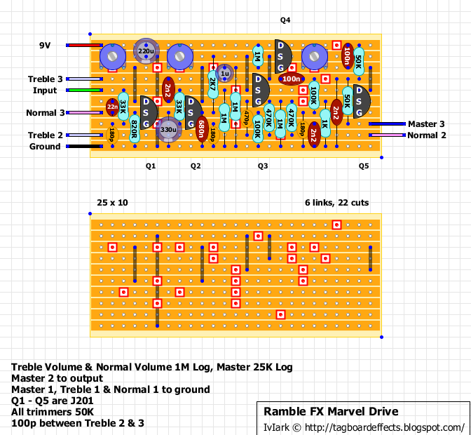
Ramble FX - Marvel Drive 1.0 [traced]
-
IvIark

- Tube Twister
Information
"If anyone is a 'genius' for putting jacks in such a pedal in the only spot where they could physically fit, then I assume I too am a genius for correctly inserting my legs into my pants this morning." - candletears7 - TGP
Much easier to read, but a couple mistakes. There is a 180pf cap to ground at the gate of Q2, and the 22n coupling cap after the 'normal' JFET should be before the 'normal' pot.jubal81 wrote:I redrew for clarity. Looks pretty reasonable. The only thing I see as weird are the parallel 220uF & 100uF caps on the source of the 'normal' j201 input.
Here's a link to the full image
[ Image ]
-
IvIark
- Tube Twister
Information
Yes someone just pointed out the 22n, this corrects it and shaves off a column.
[aarrgghh]
[aarrgghh]
"If anyone is a 'genius' for putting jacks in such a pedal in the only spot where they could physically fit, then I assume I too am a genius for correctly inserting my legs into my pants this morning." - candletears7 - TGP
HA 
Mine is not easy to read, but it´s correctly
Mine is not easy to read, but it´s correctly
-
jubal81
- Breadboard Brother
I've got this thing working. One other thing: The Source of Q4 needs to be grounded - meaning another cut to separate the drain of q5 & source of q4.IvIark wrote:Yes someone just pointed out the 22n, this corrects it and shaves off a column.
It's a pretty good sounding effect.

-
IvIark
- Tube Twister
Information
Sassinfrassinrassin!! Cheers for the heads up
"If anyone is a 'genius' for putting jacks in such a pedal in the only spot where they could physically fit, then I assume I too am a genius for correctly inserting my legs into my pants this morning." - candletears7 - TGP
-
jubal81
- Breadboard Brother
Here the corrected schematic.
Cheers to Mr. Ramble for piping in.
Great job on this. I love the plexidrive and this really gives it a run.
Cheers to Mr. Ramble for piping in.
Great job on this. I love the plexidrive and this really gives it a run.
- Attachments
-
- Ramble FX Marvel Drive 1.0 schematic
-
jalmonsalmon

- Solder Soldier
So as I see in IvIark's layout, there is only one 330uF cap on that j201's input and those other 2 electrolytic caps are not necessary?jubal81 wrote:I redrew for clarity. Looks pretty reasonable. The only thing I see as weird are the parallel 220uF & 100uF caps on the source of the 'normal' j201 input.
Saves 2 rows of vero so that's cool
Thanks all for the schemo and layout! Cannot wait to make this one.
-
IvIark
- Tube Twister
Information
The original had a 220u and 100u in parallel giving you 320u. I've just opted for a single 330u cap instead to save space as it is in keeping with the 1987X input stage. All the other caps are there.
"If anyone is a 'genius' for putting jacks in such a pedal in the only spot where they could physically fit, then I assume I too am a genius for correctly inserting my legs into my pants this morning." - candletears7 - TGP
-
mmolteratx
- Degoop Doctor
FWIW, you could substitute it with a cap as small as 10µ and have the exact same operation in the audio range, which extends pretty far below the guitar range. 330µ is crazy. Just means full gain extends down to .6Hz. 10µ means it goes down to 19.4Hz.
-
FuzzMonkey
- Breadboard Brother
Many thanks for the schematic.
-
bucksears
- Solder Soldier
Bumping this one:
How imperative is the 220uF cap on the 9V supply? Can I get by with 100uF?
I've got a 35V 220uF cap, but that thing is pretty big to fit between two trimpots.
How imperative is the 220uF cap on the 9V supply? Can I get by with 100uF?
I've got a 35V 220uF cap, but that thing is pretty big to fit between two trimpots.
-
IvIark
- Tube Twister
Information
Yes no problem using 100ubucksears wrote:How imperative is the 220uF cap on the 9V supply? Can I get by with 100uF?
"If anyone is a 'genius' for putting jacks in such a pedal in the only spot where they could physically fit, then I assume I too am a genius for correctly inserting my legs into my pants this morning." - candletears7 - TGP

-
bucksears
- Solder Soldier
Thinking about whipping up a PCB based on the schematic for this one.
It's my first vero build (always used PCBs prior) and it WORKS (technically), but the sound is VERY thick/Big-Muff like. I've got it running on 9V and the trimmers at 4.5V on the drain of the JFETs (J201s). Seems like too much compression going on - too woofy, loose in the low-end. Not at all like I heard in Brett's demo.
I'll go through it again, but there are no solder bridges and the part values are correct.
-
bucksears
- Solder Soldier
Ok, made some headway.
I replaced the J201s with 2N5457s, which is my preference (most of the time) in my BSIAB II.
This made it a GOOD distortion/OD (better than it was), but there was still something missing. I pulled the last .0022uF cap (just before the master pot) and that made a LOT of difference. It brought in a lot more presence that was missing before; I could dial up the treble pot to a little over halfway and the normal pot to about half. There is now much more 'kerrang' going on, but a bit too much treble.
That cap position MIGHT be better with either a .001uF or 560pF, if anything.
The other thing is there is still too much loose low-end in the normal channel. Turning the gain up on that is still too fuzzy, not tight.
"The other thing is there is still too much loose low-end in the normal channel. Turning the gain up on that is still too fuzzy, not tight."
That is what a real SLP sounds like. A lot of those guys back in the day ran middle and treble dimed with the bass nearly off unless they were going for the "woman tone".
As for Brett's video he clearly likes a tighter high gain sound so he probably set the Laney amp's clean channel he plugged into accordingly.